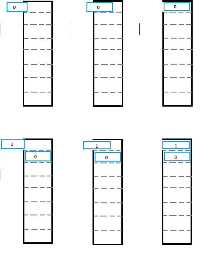
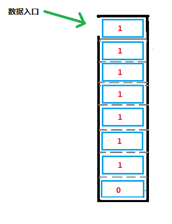
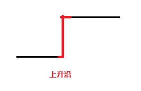
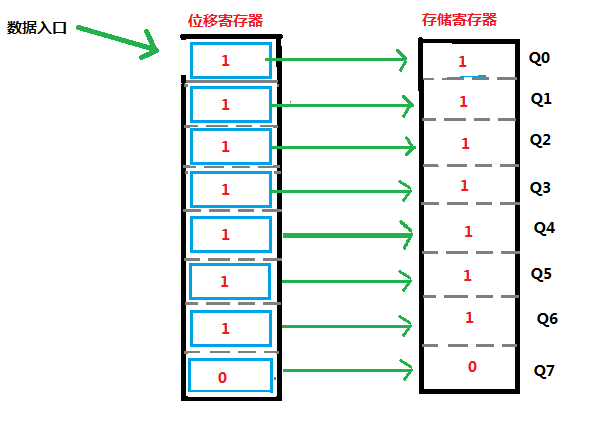
14-pin: DS(SER), serial data input pin 13 pin: OE, %20 output enable control pin, it is low-power to enable output, so connect to GND 12-pin: RCK, storage register clock input pin. On the rising edge, data is transferred from the shift register to the storage register. 11 Pin: SCK, shift register clock pin. When the rising edge shifts, the bit %20 data in the shift register is shifted back and the new bit is accepted (input from SER). 10 feet: MR, when the low level, clear the bit data that already exists in the shift register, generally do not need, accept %20 high level then. 9%20 foot %20: serial data exit pin. When the data in the shift register is more than 8 bits, the existing bit will be "squeezed out" and it is going out from here. Used for the 595 cascade. Qx: Parallel output pin The use of parameters VCC: 2V ~ 6V, 5V is best I%20Qn: +-%2035mA Note that the first bit sent from SER will go out from Q7. 74HC595 introduces a picture and a piece of text, which kind of information transmission way gives the person the first visual impact is the biggest? I think everybody has the answer in the heart. This is also the reason for the title of my article. Nonsense is here, I will use the picture below to analyze the 595 chip. The 74HC595's most important function is: serial input, parallel output. 3-state high-speed shift register (good to say) 595 has two 8-bit registers: shift register, storage register Shift Register In my opinion, the 74HC595's shift register works like a shou%20%20qiang clip. But the launch of the bullet (data in the shift register is dumped into the storage register), it is also like a bullet (because it is parallel output) Why is it like a clip? 1, serial input, the bit data has been entered in turn (so called shift register)% 20 |% 20 bullets are also a one on the first bullet, after being pressed down slowly. 2. The first input bit is the last bit in the parallel output %20|%20 that first entered the magazine's bullet and finally fired. Pinout for 74HC595 14 feet: DS, also called SER English full name is: Serial data input, as the name implies, is the serial data input port. The data source of 595 is only this one mouth, can only input a bit at a time, then input 8 times continuously, can accumulate into one byte. If we want to input the binary data 0111 1111 to the shift register of 595, let's take a dynamic picture to simulate the scene of the first 2 bits input. There are 7 frames in this picture. It has been done for a long time. After all, it is not an artist. It can be said that there are specializations in the field of surgery, there are successive ah, you still want to learn humbly :) 0111 1111 This data is completely input like this We must also pay attention to a foot: 11 feet, shift register clock input shift register clock pin. The rising edge is valid. First of all, we have to introduce the role of this pin. We know that the work of the 51 single-chip microcomputer is inseparable from the crystal oscillator. He makes the CPU work in a stable and orderly manner, just like the one who called 1,2,1 while running. The shift register clock here is also the same reason. When a new bit data comes in, the already entered bit data is shifted backwards and out of position under the control of the clock pulse of the shift register. Rising edge: The process from low to high. The shift register clock is only active during the rising edge of this process. Storage register Here we have roughly talked about how to get a bullet and put the bullets together. Here's how to fire the bullet, which is how to shift the data of the shift register to the storage register The storage register is directly connected to the 8 output pins. After shifting the data of the shift register to the storage register, Q0 Q1 Q2 Q3 Q4 Q5 Q6 Q7 can be accepted to us. Start inputting one byte of data. The so-called storage register, the data can exist in this register, and will not disappear with an output, as long as the 595 is off, there is no new The data comes from the shift register and the data remains constant and valid. After the new data comes, the data in the storage register will be overwritten and updated. 12 feet: (storage register clock input) storage register clock Data is transferred from the shift register to the storage register, which also needs the clock pulse. This is the role of the 12-pin. It is also valid for rising edges. Since then, we have explained a 595 normal workflow
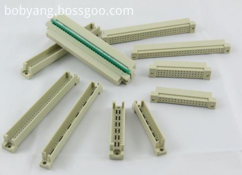
Antenk DIN41612 Connectors are a versatile two piece PCB connector set with feaures useful for many applications including connections for plug-in card and back-panel wiring, PCB to PCB attachment and peripheral connections for external interfaces. Features include a multitude of body sizes and styles with options that include selective contact loading, make and break contacts, contact lead length choices and contact plating variations each in .100" [2.54mm] or .200" [5.08mm] centerline spacing.
The DIN 41612 standard covers a series of two-piece backplane connectors widely used in rack-based telecommunication, computing, process control, medical, industrial automation, test and measurement and military/aerospace systems where long-term reliability is required. They consist of one to three rows of contacts in combinations of 16, 32, 48, 64, or 96 contacts on a 0.1-inch (2.54 mm) grid pitch. The 3 rows are labelled a, b and c and connectors up to 64 way if using a 96 way body can use either rows a+b or a+c. DIN 41612 Signal connectors can be rated to 1.5 amps per signal pin, at 500 volts, although these figures may be de-rated according to safety requirements or environmental conditions. Several hybrid power and coaxial configurations are available that can handle up to 5.6A or even 15A. This wealth of variations explains the very wide range of applications that they`re put to. For over 30 years these DIN 41612 `Euro Card` connectors to IEC 60603-2 have offered a highly reliable system for board interconnects. Precision contact density, low mating forces, a two piece protective design and many contact termination styles offer unlimited design opportunities. Termination methods include – straight PC, solder eyelet, wire wrap, crimp and [press fit" terminals. Insertion and removal force are controlled, and three durability grades are available. Standardisation of the connectors is a prerequisite for open systems, where users expect components from different suppliers to operate together; ept and Conec DIN 41612 are therefore fully intermateable with all other similarly compliant products from other manufacturers like Harting, Erni, Hirose and TE Connectivity, etc.
DIN 41612 Connectors are widely used in rack-based electrical systems. The standard performance of these connectors is a 2 A per pin current carrying capacity and 500 V working voltage. Both figures may be variable due to safety and environmental conditions.
Types
Features and Benefits of Din41612 Connector:
Uses
Applications of Din41612 Connector:
Din41612 Connectors,Din 41612,Eurocard Connector Din41612,Male Din41612 Connector ShenZhen Antenk Electronics Co,Ltd , https://www.pcbsocket.com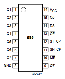
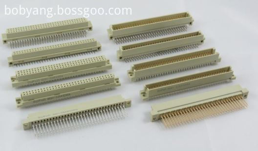
The most common connector in the DIN product line is type C, which is widely used in VMEbus systems, the DIN 41612 standard has been upgraded to meet international standards IEC 60603-2 and EN 60603-2. In the past, ept used a comb supported press-fit tool for their type C and B press-fit female connectors. To be more competitive, ept has changed to flat-rock technology (just a flat piece of steel pushed on the top of the connector) as used by many other manufacturers.
Number of contacts varies
Many variations of housing material, including different types of metal and plastic
Both angled and straight versions
Male and female
C,R,B,Q Type DIN41612 Connectors
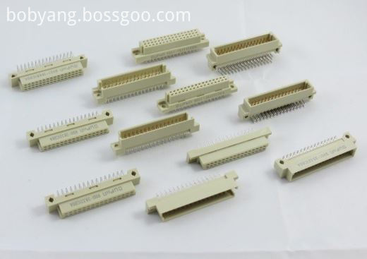
Half C, R, B & Q Type DIN41612 Connectors
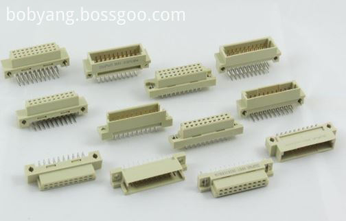
1/3 C,R, B & Q Type DIN41612 Connectors
H, F, H+F & M type DIN41612 Connectors
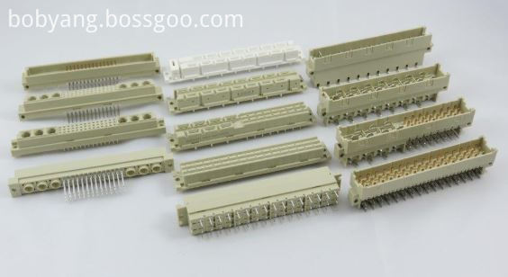
IDC Type DIN41612 Connectors
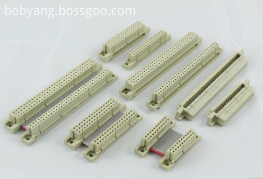
Female Cable Connector
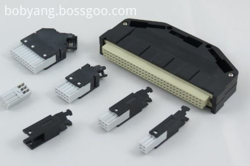
High Pin Count DIN41612 Connectors
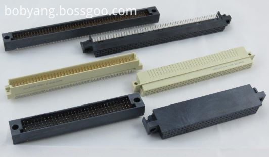
Shroud DIN41612 Connectors
• Indirect mating (male/female)
• Automated production processes
• Continuous quality assurance
• 3-160 contacts
• Complete interconnection system
• Numerous interface connectors
• A wide variety of hoods
• Many termination technologies provide for the lowest installed cost
• Contacts selectively gold-plated
• Tinned terminations for increased solderability
The primary use of DIN 41612 connectors are PCB Connectors and motherboards, the main acceptance would be their board to board reliable connections.
Applications
• Data centers
• Storage
• Servers
• Base stations
• Telecommunications equipment
• Backplane and motherboard assemblies
• Switching systems
• Modular rack systems
• Power automation
• Distributed control systems in
industrial control
• Programmable logic controllers (PLC)
• Robotics
• Test and lab equipment
• Energy distribution
• Monitoring equipment
This is not a definitive list of applications for this product. It represents some of the more common uses.