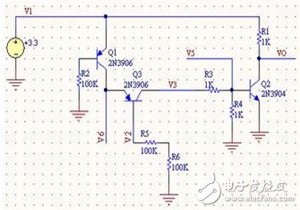
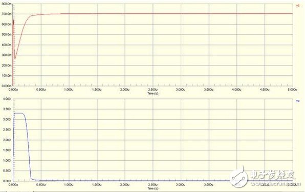
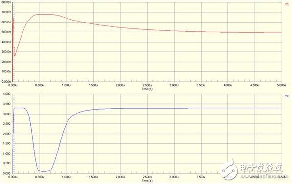
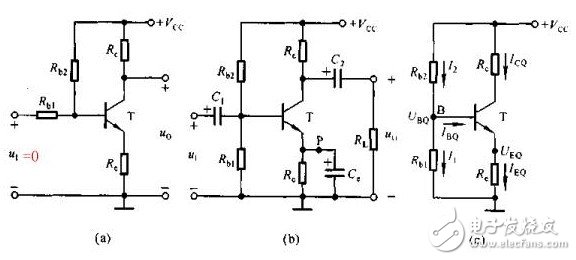
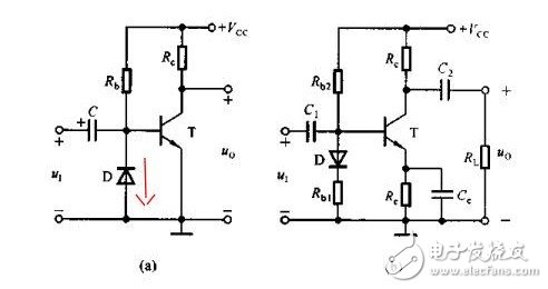
Switching device In the embedded circuit, the IO port is often used to control the switching function of some circuits, and the triode can be used as a switching device. When used as a switching device, a switching transistor such as a low-power device such as 9014 and 9015 is required, and the transistor is in a saturated state. Here is an example to illustrate the characteristics of this type of circuit: The simulation circuit diagram is not complete. The circuit is a crystal oscillator shutdown function circuit, in which the VO is connected to the MCU crystal oscillator input terminal (XIN). If the bases of Q1 and Q3 are low at the same time, Q2 is turned on and VO is 0, causing the crystal oscillator to stop and shut down the processor. We analyze R3 and R4 (actual circuit 470K) so that Q2 and Q3 are in a saturated state; Q3 is the Q1 collector load, and Q1 can be controlled to be in a saturated or amplified state when the R5 resistance is adjusted. In order to make the base of Q2 turn on, it is necessary to make Q1 provide enough current to meet the condition, and only Q1 is in the amplified state to satisfy the condition; When R5=100K, the simulation diagram is as follows: When R5=470K, the simulation diagram is as follows: From the above analysis, it can be concluded that the Q2 can be turned on and the crystal is turned off only when the current is large enough. The above is a more complicated combination switch circuit. power component In the embedded circuit design, the power amplifying circuit is rarely used. After reading the contents of the transistor of the university's electro-mechanical teaching materials yesterday, I felt that although the model was good, but after rereading, I found out that it was just rote memorization. Really comprehend. The static working point not only determines whether it will be distorted, but also affects dynamic parameters such as voltage amplification and input resistance. However, in the actual circuit, the static working point is stabilized due to the change of the ambient temperature, so that the dynamic parameters are unstable, and the circuit may not work normally. In all environmental factors, the temperature has the greatest influence on the dynamic parameters. As the temperature rises, the transistor magnification becomes larger and the ICE becomes significantly larger. Taking the common emitter circuit as an example, when the temperature rises, the Q point will move toward the saturation region; when the temperature decreases, the Q point will move toward the cutoff region. The following figure is a typical static operating point circuit Figure AB has the same equivalent DC circuit. In order to stabilize the Q working point, it is usually necessary to satisfy I1" IBQ. VBQ = Rb1 * VCC / Rb2 + Rb1 By designing this way, VBQ will remain basically unchanged regardless of the change in ambient temperature. When the temperature rises, the ICE becomes larger, and the VEQ becomes larger. Because VBE = VBQ - VEQ, the VBE will become smaller; since the VBE becomes smaller, the IBE will also become smaller, and the ICE will become smaller. The use of RE introduces DC negative feedback to make the Q operating point more stable. Generally speaking, the stronger the feedback, the more stable the Q point. Other stable Q operating point circuits The above is a circuit that performs temperature compensation using diode direction characteristics and forward characteristics. For Figure A, because IRB = ID + IBE, the ICE and ID become larger as the temperature rises (the direction current increases with temperature), which will cause the IBE to decrease and cause the ICE to decrease. phone Charging cable,Usb Phone Data Cable Android,iphone charge data cable,Phone data cable adapter Dongguan Bofan technology Co., LTD , https://www.pengliandz.com