![]()
Probe current voltage pin 420*4450 head diameter 5.0 over current current and voltage pin
![]()
Test - lowercase jpg
![]()
Kaixin micro test
![]()
GW MB10F 0.8A 1000V rectifier bridge
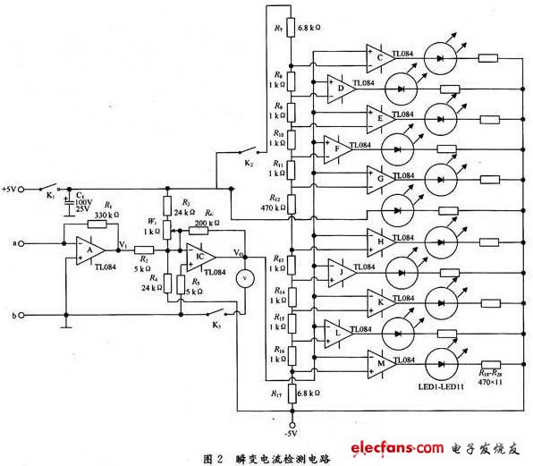
The circuit principle of the transient current detector is shown in the figure. The TL084 junction FET input operational amplifier is selected. Each of the operational amplifiers uses a high voltage junction FET and a bipolar transistor on a single integrated circuit, which is compatible with better matching and has a high conversion rate. The input base current and input drift current are small, and the drift voltage temperature coefficient is low. The integrated operational amplifier A and R1 form a short-circuit current amplifier, and B and R2 to R6 and W1 form an inverting adder, which amplifies the output voltage V1 of the operational amplifier A, wherein R3, R4 and W1 form a circuit, if input i When =0, the output voltage VO≠0 of the operational amplifier B can move the movable contact of the multi-turn potentiometer W1 to make VO=0. In fact, W1 is equivalent to the function of the pointer galvanometer zero adjustment knob. The voltage amplification factor of the operational amplifier B is AV=-R6/R2=-40. R7 ~ R17 series voltage divider produces 10 reference voltages, each integrated operational amplifier is connected to a voltage comparator, and a level indicating circuit is formed with a resistor and a light emitting diode. When there is an input current i, the output voltage of the operational amplifier A is V1=-i?R1, and the voltage is amplified by an amplifying circuit composed of B and R2 to R6, W1, and compared with a reference voltage of the voltage comparator, and is composed of a light emitting diode. The level indicating circuit synchronously reflects the relative magnitude, direction and variation law of the current flowing between the terminals a and b. The five voltage comparators of the op amps C to G have their inverting input terminals connected to the reference voltages of 1.918 9 V, 1.465 8 V, 1.012 7 V, 0.559 6 V, 0.106 5 V, and the non-inverting input terminals are connected to the amplifier B. The output VO is used for comparison display of forward current (ie, flowing from the a terminal and flowing from the b terminal). The non-inverting input terminals of the other five voltage comparators are respectively connected to the reference voltage, -0.16 5 V, -0.559 6 V, -1.012 7 V, -1.45 8 V, -1.99 9 V, and the inverting input terminals are connected to the output VO of the amplifier. For comparison of negative current (ie, flowing from the b-end and flowing out at the a).

FPCB
A flexible printed circuit board is a type of PCB designed to meet the needs of flexible electronic circuits. Originally designed flexible printed circuits to replace traditional wiring harnesses.
Flexible printed circuits are produced using flexible laminates. The flexible laminate holds the conductive foil as well as the dielectric substrate. Flexible circuit boards can be three-dimensionally routed and can be appropriately shaped to fit the available space.
Flexible PCB,Flexible Circuit Board,PCB Production Process,PCB Process Technology,Circuit Board Manufacturing Process
Huizhou Liandajin Electronic Co., Ltd , https://www.ldjpcb.com
