Anti-microbial Hydrogel Screen Protector
Bacteria are everywhere in our daily lives. Mobile phones have become an indispensable item for us. Of course, bacteria will inevitably grow on the phone screen. The antimicrobial coating used in our Anti Microbial Screen Protector can reduce 99% of the bacterial growth on the screen, giving you more peace of mind.
Self-healing function
The Screen Protector can automatically repair tiny scratches and bubbles within 24 hours.
Clear and vivid
A transparent protective layer that provides the same visual experience as the device itself.
Sensitive touch
The 0.14mm Ultra-Thin Protective Film can maintain the sensitivity of the touch screen to accurately respond to your touch. Like swiping on the device screen.
Oleophobic and waterproof
Anti-fingerprint and oil-proof design can help keep the screen clean and clear.
If you want to know more about Anti Microbial Screen Protector products, please click Product Details to view the parameters, models, pictures, prices and other information about Anti Microbial Screen Protector products.
Whether you are a group or an individual, we will try our best to provide you with accurate and comprehensive information about Anti Microbial Screen Protector!
Antimicrobial Screen Protector, Anti-microbial Screen Protector, Anti-bacterial Screen Protector, Antibacterial Screen Protector,Anti-microbial Hydrogel Screen Protector Shenzhen Jianjiantong Technology Co., Ltd. , https://www.jonsun-sz.com
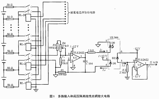
Multiple input and signal conditioning circuits are shown in Figure 1.
In Figure 1, TIL300 is a light-coupled device for isolation and amplification of AC and DC signals. The main technical indicators are as follows:
* Bandwidth > 200kHz;
* Transmission gain stability is ±0.05%/°C;
* The peak isolation voltage is 3 500V.
C104 is a 0.1μF monolithic capacitor that prevents oscillations in the circuit. The internal D0 of the TIL300 is a light-emitting diode, and its current operating point If can be selected as 10 mA. D1 and D2 are photodiodes which are excited by D0 to generate currents Ip1 and Ip2, respectively, whose magnitude is related to If:
Ip1=K1·If
Ip2=K2·If
Among them, K1·If and K2·If indicate the change rule of Ip1 and Ip2 with If, which can be called optical coupling function. Since D1 and D2 are made by the same process and packaged with D0, the variation of their optical coupling functions is quite uniform, so it can be set:
K=Ip2/Ip1=(K2·If)/(K1·If) (1)
In fact, K can be regarded as a constant, and the value of K is the electrical parameter of TIL300, and the typical value is 1. The parameter range is from 0.75 to 1.25. 
U1 constitutes a negative feedback amplifier whose voltages at the non-inverting input and inverting input should be approximately equal, ie, satisfy equation (2):
Vi≈Ip1·R1 (2)
U3 is an emitter follower with high input impedance and the output voltage Vo is waiting for the input voltage:
Vo≈Ip2·R2 (3)
The gain of the high voltage isolated linear optical coupling amplifier circuit can then be calculated by equation (4):
Vo/Vi=(Ip2/Ip1)·(R2/R1)=K(R2/R1) (4)
Since the measured battery voltage is divided by R3, R4, and R5 and then input to the U1 non-inverting terminal,
Vi=E·[R5/R3+R4+R5]] (5)
E is the terminal voltage of the battery, from which:
Vo=K·(R2/R1)·[R5/(R3+R4+R5)·E (6)
Equation (6) shows that Vo and E are linear.
The I+12V is an independent power supply for the input sections of the U1 and TIL300; ±12V is also an independent power supply for the output sections of the U3 and TIL300. The isolation of these two power supplies has a great influence on the high-voltage isolation performance of the circuit. Two sets of coils with good insulation from each other in the power transformer should be used.
The 50Ω resistor connected in series with the input terminal of the micro relay is the current limiting resistor in the measuring circuit to prevent accidental short circuit or poor insulation, causing excessive current to burn the device or destroy the battery. Due to the high input impedance of the U1 op amp, the 50Ω current-limiting resistor has no effect on the measurement accuracy. These current limiting resistors should select a metal film resistor with a power value greater than 1W.
The adjustment potentiometer R4 can be adapted to the battery with different terminal voltages.
Due to space limitations, other circuits are not introduced.
The actual operation shows that the circuit refurbishment system is in good condition.