1. Structural principle of B-ultrasound system B-type ultrasonic diagnosis system is divided according to its structure: it is mainly composed of probes, transmitting and receiving circuits, analog signal processing circuits, keyboard control circuits, digital scanning converters, image display circuits and power supply circuits. Probes can be divided into linear array scanning probes and phased array scanning (fan scanning) probes according to their different scanning methods. The basic principle of linear array scanning is: several vibrators are arranged in a linear array to form a linear array transducer, which is controlled by an electronic switch, which is combined in time-sharing, works in turn, and sequentially excited from one side of the probe to another Generate synthetic beam transmission and reception. The basic principle of phased array scanning is: the vibration elements arranged in the linear array are not simultaneously excited, and the excitation pulse applied to each vibration element has an equal time difference, so that the direction of the synthesized beam and the plane of the vibration element arrangement There is a phase difference in the normal direction, and the time difference changes uniformly, and the phase difference also changes accordingly. Through the time control, the phased array scanning of the ultrasonic beam is realized, that is, the sector scan. B-mode ultrasonic diagnostic equipment uses brightness modulation to display the reflected echoes of all interfaces in the depth direction. In the horizontal direction, a fast scanning method is used to successively transmit and receive ultrasonic echoes to obtain a vertical planar two-dimensional ultrasonic tomographic image, that is, a line-scan tomographic image. If fast scanning is performed by changing the angle of the ultrasonic beam, a vertical fan-face two-dimensional ultrasonic tomographic image, that is, a fan-swept tomographic image, is obtained. The transmitting circuit provides the excitation voltage to the probe, and realizes the scanning and focusing of the ultrasonic system beam through the control and excitation delay of different permutations and combinations of the vibrating elements, and the receiving circuit performs phase-shift synthesis on the ultrasonic echo signal. The analog signal processing circuit includes a preamplifier, a TGC circuit, a dynamic filter circuit, a logarithmic amplifier circuit, and so on. The ultrasonic echo signals obtained by the image detection circuit and the Doppler detection circuit are further processed by the scan converter. The essence of the digital scan converter is a digital image processing system with image memory. The main function is to realize the digitization of ultrasonic signals. And then proceed to process, and finally realize TV display on the monitor. The image processing circuit includes gradation processing, histogram processing, data interpolation processing and other circuits. The main purpose is to improve the quality of the image. 2. Trouble repair skills of B-type ultrasonic diagnosis system First of all, the reason for the failure of the B-type ultrasonic diagnostic system is mainly due to the large workload of B-ultrasound and the poor environmental conditions, such as the influence of factors such as temperature, dust, power fluctuation and interference, which can increase the failure rate of the instrument. Strengthening the daily maintenance work is an indispensable part of the maintenance work of the B-type ultrasound diagnostic system. In the hands-on repair of faults, in general, swapping the color ultrasound and black and white B-mode ultrasound circuit boards can be used as a way to query the fault. The skills and methods that need to be paid attention to in the maintenance mainly include the following aspects: Welcome to reprint, this article comes from the electronic enthusiast network (http: //) First, before performing specific maintenance work, as a professional engineering technician engaged in B-ultrasonic maintenance work, you should first be familiar with the working principle and specific circuit structure of this machine, which will help to understand the essence of the fault Various phenomena manifested by the fault. Improve maintenance quality. Second, before performing specific maintenance, you should first be familiar with the main functions of the instrument and the various functional operations related to maintenance. In this way, in terms of various functions and the interrelationship between various functional operations, it helps to narrow down the fault range, find the fault location of the instrument, and shorten the maintenance time. Third, before performing maintenance, you should carefully observe and investigate various phenomena before and after the failure, especially to understand the process and background of the failure from the operator. B-type ultrasound is a large and expensive instrument, and the maintenance work is a complicated Engineering, without fully understanding the fault situation and accurately judging the nature of the fault, should not take the risk of repair. Fourth, the power supply part is one of the frequently occurring parts of the B-ultrasound diagnosis system. Due to the large power consumption and high temperature of the power supply part, the failure rate is also high. The manifestations of power failures are also diverse, often manifested as functional failures of the entire system or a certain part of the system. The malfunction of the instrument due to the interference introduced by the power supply part is also such a failure. In most cases, you should first check whether the power supply is working properly. Fifth, the peripheral part of the ultrasound diagnosis system is also one of the frequently failed parts, but the peripheral part is relatively intuitive, the structure is not complicated, and each part is relatively independent, and the fault diagnosis and positioning are relatively easy. Such as monitors, trackballs, printers, etc., I realized in the maintenance, the elimination of such faults should be relatively simple. Sixth, for the remaining components of the ultrasonic diagnostic system, such as various system circuit boards, due to the high degree of circuit integration, most of them are special devices, usually only board-level maintenance, in the process of fault diagnosis, According to the circuit principle, combined with the operator's description of the fault background and fault phenomenon, the fault code displayed by the instrument, his own understanding and investigation of the fault phenomenon of the instrument, and other comprehensive judgments to determine the fault location. In the case of B-ultrasonic machines of the same or near model, the same circuit board can be found and swapped for fault finding. Welcome to reprint, this article comes from the electronic enthusiast network (http: //)
PVC insulated shielding installation
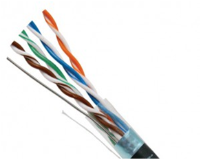
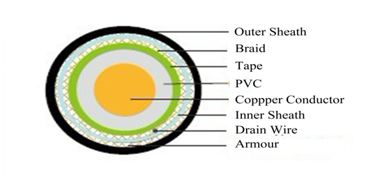
cables(wires) are electrical cables that contain
insulating conductors encased in a standard conductive layer. It features an
outside layer or [shield" of conductive material around the internal
conductors, which is connected to earth. The shield can be made from strands of braided copper (or a similar metal), a spiral copper tape, or some other
conducting polymer. The conductive
shield can reflect or conduct external interference away without it
affecting the signals in the internal conductors. This cable is most often
found in industrial settings and installations where other nearby equipment is
likely to generate electromagnetic interference (EMI).
Advantages:
Standard:
GB/T8734-2016
Rated Voltage:
300/300V
Application:
In security systems, this can help prevent false alarms
generated by interference.
For audio applications, shielding can help reduce noise
and static in the projected sound.
Welcome to visit our factory to learn more about us. If
you have any questions, please feel free to contact us.
PVC Insulated Shielding Installation Wire PVC Insulated Shielding Installation Wire,PVC Insulated Flexible Shielding Installation Wire,Electrical Cable Insulation Types,PVC Insulated Shielding Installation Electric Wire Fujian Lien Technology Co.,Ltd , http://www.liencable.com
