Many modern audio amplifier designs do not consider high frequency RF issues, and these amplifiers are increasingly exposed to strong RF interference environments. For audio amplifier designs that do not address RF interference, the RF carrier information is demodulated to the audio band.
A very prominent example is the GSM (Global System for Mobile Communications) cellular telephone system. The GSM standard uses Time Division Multiple Access (TDMA) to enable simultaneous communication between multiple handsets and a base station. The GSM handset transmits data at a burst rate of 217 Hz, producing a strong electric field modulated by a 217 Hz frequency, just in the audio band. Although the GSM handset operates in the 800MHz to 1900MHz frequency range, the 217Hz envelope is fixed.
The amplifier in the GSM handset must be able to reject the 217 Hz envelope frequency of the RF carrier or completely shield its electric field. The lead between the amplifier and the audio source is equivalent to the antenna. The antenna effect is most pronounced for frequencies where the 1/4 wavelength matches the lead length. For a 900 MHz signal, the 1/4 wavelength is 7.5 cm; for a 1900 MHz signal, the 1/4 wavelength is 3.5 cm. Therefore, a lead having a length close to the above two specifications is most sensitive to an interference signal of a nearby power amplifier, and a strong interference signal is received.
As the number of mobile phone audio amplifiers continues to increase, the above problems become more apparent. Stereo headphone amplifiers provide sound and music signals to external headphones; stereo speaker amplifiers provide amplification and playback, taking care to ensure that each audio amplifier is not affected by the RF energy emitted by the mobile phone. Although both the speaker and the headphone amplifier can receive RF signals, the headphone amplifier has a lower signal amplitude and more complicated problems. Fortunately, there are several ways to reduce the impact of RF noise on the amplifier.
Option 1 - Integrate the audio amplifier into the baseband IC
One way to improve the RF sensitivity of a headphone amplifier is to integrate the headphone amplifier into the baseband processor, which reduces the lead length between the audio source and the amplifier. This solution not only reduces the antenna effect, but also improves the integration of the circuit. Since the input does not have an antenna effect at the sensitive frequency, RF interference with the audio signal is avoided.
Although integrated technology can reduce the system's RF sensitivity, baseband processors typically use low-cost headphone amplifiers that can degrade sound quality to some extent. In addition, these amplifiers are powered from a single supply and have a bias on the output signal at around VDD/2. Straightening capacitors are required to connect these signals to the headphone speaker, while the DC blocking capacitors occupy a large PCB area, reducing the low frequency response of the system and causing distortion of the audio signal.
Because the headphone amplifier in the integrated solution is close to the baseband processor, the sensitive analog circuitry is close to the noisy digital circuitry, which in turn increases the noise output of the amplifier. Ultimately, the integration scheme also increases the difficulty of the headphone amplifier ground layout, thereby reducing system sound quality.
Option 2 - Improve input and power wiring
In order to avoid problems caused by integrated headphone amplifiers, a dedicated headphone amplifier IC must be selected. Even with a headphone amplifier that is not designed to suppress RF noise, careful layout of the board results in good sound quality and low RF sensitivity. The leads at the input are most likely to affect the RF sensitivity. These leads should be placed between the two layers to shield the external RF electric field. In order to reduce the antenna effect of the input leads, the leads must be shortened as much as possible so that the lead length is much smaller than the 1/4 wavelength of the sensitive frequency.
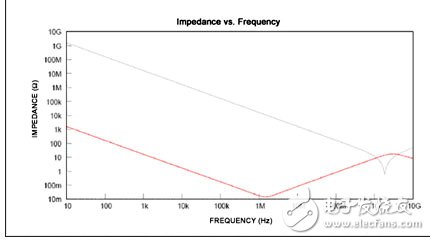
Amplifier power is also a way to pick up RF noise. Board designs typically use bypass capacitors to reduce power supply noise, but at RF frequencies, self-induction of these capacitors reduces the performance of high frequency waves. Figure 1 shows the impedance versus frequency for 1μF and 10pF ceramic capacitors. In the audio range, the 1μF capacitor has low impedance to ground and has good noise suppression. When the frequency is higher than 1 MHz, the impedance generated by the self-inductance is higher than the capacitive reactance, so that the impedance is increased. If a 10pF capacitor is connected in parallel with a 1μF capacitor, the small capacitor bypasses the self-inductance of the 1μF capacitor from 800MHz to 1900MHz in the GSM frequency range.

Figure 1. The amplifier's power cord picks up the RF signal.
The data in the figure shows that the impedance of the 1μF capacitor to ground is lower than the impedance of 10pF, providing better noise suppression.
Option 3 - Using RF Suppression Amplifier
RF sensitivity can be overcome to some extent with integrated processor/amplifier or through board layout, but a simpler solution is to use a headphone amplifier that is less susceptible to RF electric field interference. The MAX9724 is an amplifier designed to reject RF noise and solve RF sensitivity problems without the need for a special board design, which greatly simplifies product development and reduces costs.
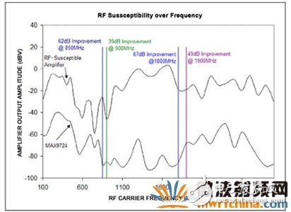
Figure 2 shows a comparison of the MAX9724 with a normal audio amplifier. To test RF sensitivity, an amplifier (mounted on a PCB that is not modified for low sensitivity) is placed in an isolated RF cavity that can create a controllable electric field in an environment without other electric fields. In the RF cavity, the RF signal creates an electric field between the two plates. For the RF sensitivity test, an electric field of 50 V/m was applied to the PCB at 100 MHz intervals between 100 MHz and 3 GHz. The 50V/m electric field was chosen because it simulates the field strength that the device may encounter in practical applications. 100% amplitude modulation of the RF carrier with a 1 kHz sine wave produces the worst operating conditions for the amplifier test. The noise measured at the output of the amplifier is the amplitude of the 1 kHz envelope after demodulation of the amplifier.

Figure 2. Data shows that the MAX9724 effectively reduces the RF sensitivity of the amplifier compared to a normal amplifier.
At the GSM critical frequency, the MAX9724's immunity to interference is at least 39dB higher than comparable amplifiers. Assuming that the amplifier output is -70dBV or lower, it is almost quiet, or the human ear does not feel the noisy environment, and the MAX9724 can reach or fall below this noise level throughout the GSM band. Ordinary amplifiers output audible noise at all RF test frequencies.
in conclusion
RF sensitivity is a key issue for mobile audio amplifiers. Although integrating a headphone amplifier into a baseband processor can help solve this problem, the specific solution often requires sacrifice of fidelity. There are two ways to suppress RF noise using an external headphone amplifier (Schemes 2 and 3 above):
Reducing the RF energy of the input amplifier by shielding and shortening the input signal leads;
Select an amplifier with RF suppression to minimize noise coupled to the output.
In some cases, RF sensitivity can be substantially reduced by using only one of the above techniques. Even so, you should use a headphone amplifier with RF suppression and carefully plan the board to solve the tough problems in the system.
Withstand high voltage up to 750V (IEC/EN standard)
UL 94V-2 or UL 94V-0 flame retardant housing
Anti-falling screws
Optional wire protection
1~12 poles, dividable as requested
Maximum wiring capacity of 4 mm2
Feed Through Terminal Block,T12 Series Terminal Blocks,Terminal Strips Connector,Cable Connectors Block
Jiangmen Krealux Electrical Appliances Co.,Ltd. , https://www.krealux-online.com