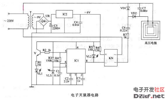
Homemade high-voltage electronic rodenticide (including working principle) The electronic rodent control device described in this paper adopts the infrared light reflection control circuit, which can automatically turn on the working power of the high voltage circuit when the mouse enters its effective detection range, and generates high voltage to kill the mouse. Circuit Operation Principle The electronic rodent circuit consists of a power supply circuit, an infrared control circuit, and a high voltage circuit, as shown in the figure. In the circuit, the power supply circuit is composed of a power transformer T, a rectifier bridge stack UR, a filter capacitor C4, C5, and a three-terminal voltage regulator integrated circuit IC2; the infrared control circuit consists of an infrared light emitting diode vLI, an infrared photodiode VLS, a transistor V, and a resistor R1. A R6, a capacitor C1 - C3, an integrated circuit IC1, a light emitting diode VL2 and a solid state relay KN; the high voltage is composed of a solid state relay KN, a resistor R7, capacitors C6, C7, diodes VD1, V D2 and a high voltage electrode. After the AC 220V voltage is stepped down by T, UR rectified, C5 filtered and IC2 regulated, the operating voltage of the infrared control circuit is +6V. The oscillating signal outputted by the 5-pin of IC1 is amplified by V, and VL1 is driven to emit modulated infrared light. Usually (when no mouse enters the infrared detection area), V LS can not receive the infrared light emitted by VLl, IC 1 is in automatic oscillation state, its 8 feet output high level, VLZ is not bright, KN and high voltage circuit do not work. When a mouse enters the infrared detection range, the infrared light reflected from the mouse body is received by VD1, so that the 8 pin of IC 1 changes from high level to low level, VL2 lights up, KN energizes, and high voltage is generated on the high voltage electrode. Kill the mouse. When the dead mouse is removed (the power should be cut off), the VLS is turned off again. The 3 pin of IC1 loses the input signal, the 8 pin becomes high level, V L2 goes out, the KN and the high voltage circuit stop working, and the circuit returns to the waiting state. Component selection R1 - R6 selects 1/4W metal membrane resistor or carbon membrane resistor for use; R7 selects 2W metal membrane resistor for use. C1-C4 selects monolithic capacitors; C5 selects aluminum electrolytic capacitors with a withstand voltage of 25V; C** C7 selects CBB capacitors with a withstand voltage of 1000 V. VLS selects PH302 or BPW82 type infrared photodiode; VD1 and V D2 select 1 N4007 type silicon rectifier diode. VLl selects IR333 or SE303 and other types of infrared light-emitting diodes; VL2 selects 5mm ordinary light-emitting diodes. V selects the 59013 or 3 DG9013 type silicon NPN transistor. IC1 selects LM567 or NE567 type integrated circuit; IC2 selects LM7806 type three-terminal regulator integrated circuit. KN selects SP2110 or JGX-2F solid state relay. The high voltage electrode can be made using a thin bare metal wire or a copper plate. This circuit is directly connected to the city, and must pay attention to the safety of itself and others. Brake Disc Brake Disc,Car Brake Disc,Automobile Brake Disc,Auto Brake Disc Zhoushan Shenying Filter Manufacture Co., Ltd. , https://www.renkenfilter.com