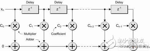
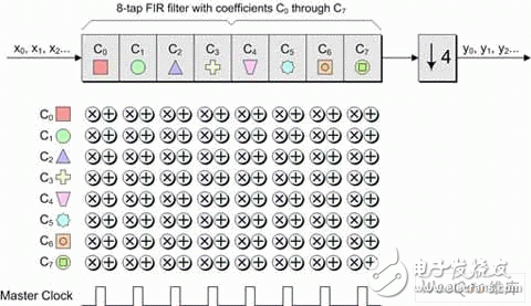
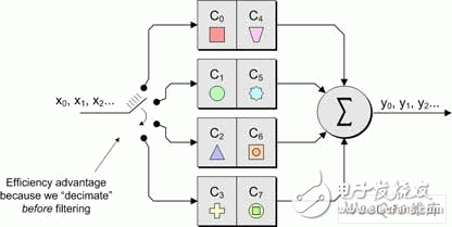
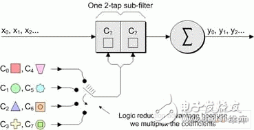
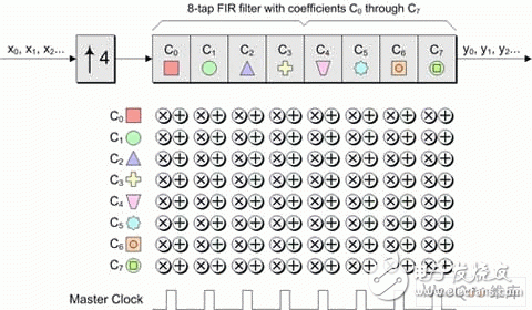
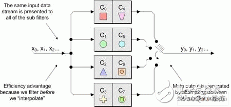
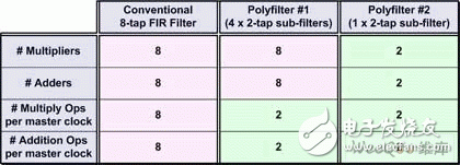
In modern electronic systems, digital signal processing (DSP) applications can be seen everywhere, from MP3 players to digital cameras to mobile phones. One of the pillars of the DSP designer's toolbox is the finite impulse response (FI) filter. The longer the FIR filter (with a large number of taps), the better the filter response. However, there are trade-offs here, as a large number of taps increase the need for logic, increase the computational complexity, increase power consumption, and possibly cause saturation/overflow. Multiphase techniques can be used to implement filters, have comparable results to traditional FIR filters, and use less logic, require less computational resources, lower power consumption, and reduce possible saturation/overflow. These filters can be implemented with today's new small-scale, mid-range FPGAs such as LATTICEECP3. Entering the DSP world can be a little daunting, so let's start with some simple concepts. For digital systems, such as audio, video, and wireless, the resulting signal is related to the sample rate. For example, a professional audio signal is sampled at 48 kHz (ie 48,000 samples per second). In contrast, consumer CD players use a sampling rate of 44.1 kHz. Multirate systems use multiple sample rates. In some cases, a portion of a system running at a certain rate requires a signal that was originally sampled at another rate (converting professional audio to consumer CD audio is an example). In this case, the rate of the original signal must be increased or decreased as needed. Or for a specific use, it is possible to sample the original data at a higher rate than actually needed. Therefore, reducing the sampling rate and then running the resulting data can significantly reduce data throughput requirements, reduce memory requirements, improve processing efficiency, and reduce power consumption. Let us first consider the problem of reducing the sampling rate. Suppose we have a signal that was originally sampled at a frequency we call fHz, as shown in Figure 1. Figure 1 Sampling the original signal with a sampling rate of f Hz Now suppose we want to reduce the sampling rate to 1/4 of the original frequency. One way to do this is to simply throw away three of every four original samples, as shown in Figure 2. Figure 2 Get a new signal with a 1/4 f Hz sampling rate In digital signal processing, "aliasing phenomenon" refers to a situation in which different continuous signals are difficult to distinguish from each other when sampling, and they are "aliased" with each other. Aliasing is also known as distortion, or artifacts, where the signal derived from sample reconstruction is different from the original continuous signal. If we discard some of the samples as discussed above, the resulting signal will contain artifacts of aliasing. As a simple example, consider an audio signal that may contain music from high-frequency components that are inaudible to the human ear. If we sample this signal at a too low rate (when we discard some samples, we are actually doing what we are doing), and then reconstruct the music with a digital-to-analog converter, we can hear the undersampled high-frequency components. Low frequency aliasing. To avoid this, it is common practice to remove unwanted high frequencies with a low pass filter before discarding unwanted samples, as shown in Figure 3. Figure 3 Filtering this signal before discarding any samples In general, "downsampling" simply refers to the operation of discarding the processing of a sample without performing filtering. In contrast, "decimation" refers to the entire process of reducing the sampling rate, that is, performing a filtering operation and then discarding the sample. In fact, "downsampling", "downconversion" and "decimation" are often used interchangeably. The "decimation factor" is the ratio of the input sample rate to the output sample rate. Usually indicated by the letter M. In the above example, the input rate is 4 times the output rate, so M=4. The situation now considered is that we want to increase the sampling rate. The reason for this is to have another part of the system run at a higher sampling rate with the signal. Suppose we start with a signal that is originally sampled at a frequency we call fHz, as shown in Figure 4. Figure 4 Original signal with a sampling rate of f Hz Now suppose we want to increase the sampling rate by 4 times the original frequency. We begin to insert zero-value samples between the original samples to increase the sample rate, as shown in Figure 5. Figure 5 Augmenting the original signal with a zero-valued sample But now there is a problem because the new zero-value sample adds unwanted spectral components to the signal. To solve this problem, we filtered this new signal, removing the unwanted components and producing a more appropriate sample value, as shown in Figure 6. Figure 6 sample rate is 4 times fHz final signal Technically, “upsampling†simply refers to the process of inserting a zero-valued sample. In contrast, "interpolation" refers to the entire process of increasing the sampling rate, that is, inserting a zero-valued sample and then performing a filtering operation 1. In fact, "upsampling", "upconversion" and "interpolation" are often used interchangeably. "Interpolation factor" refers to the ratio of the output sample rate to the input sample rate. This is usually indicated by the letter L. In the above example, the output rate is 4 times the input rate, so L = 4 . See Figure 7 for a graphical illustration of this process. Figure 7 Filtering this signal after inserting a zero value sample In the previous discussion, it should be noted that the decimation and interpolation factors can be assumed to be only integer values. That is, we can only extract or interpolate integer factors instead of fractional factors. For example, if decimation is performed, we can only discard samples of integers (1 of 2, 1 of 3, 2 of 3, 3 of 3, etc.). Suppose we want to modify the sampling rate of the signal to interface between the two subsystems. If the ratio of the sampling rate of the subsystem is an integer value, then we only need to perform the extraction or interpolation. However, if the ratio of the sample rate is a fractional value, then we need to combine the decimation and interpolation. This process is called resampling. For example, if resampling is performed with a factor of 2.5, we first use an interpolation factor of 5 and then use a decimation factor of 2 to produce a sample rate with an input sample rate of 5/2 = 2.5, as shown in Figure 8. Figure 8 resampling (L = 5, M = 2) In practice, the interpolation and decimation filters as shown in Figure 8 will be combined. The term "resampling factor" refers to the ratio between the output sample rate and the input sample rate. Regardless of the frequency involved, this can be expressed as the ratio between the interpolation and the decimation factor L/M, which in the above example is 5/2 = 2.5. As another example, consider the process of resampling a professional audio signal with a sampling rate of 48 kHz, and for consumer audio equipment, a sampling rate of 44.1 kHz is required. In this case, the resampling factor is equal to the ratio of output rate to input rate: 44.1 kHz /48 kHz = 0.91875. Looking at another method, the sampling rate must be changed from 48,000 Hz to 44100 Hz, which means the input-to-output ratio is 44100/48,000 == 441 / 480 = 147 / 160. Since there are no common factors in 147 and 160, we have to stop there, which means we need an interpolation factor of 147 and then a factor of 160, as shown in Figure 9. Figure 9 Resampling commercial audio (L = 147, M = 160) Again, the resampling factor can be expressed as the ratio between the interpolation and the decimation factor L/M, which is 147/160 = 0.91875. Not surprisingly, this is exactly the same value we get from the input and output sample rates because the required interpolation and decimation factors are derived from these ratios. There are two basic types of digital filters: finite impulse response (FI) and infinite impulse response (IRR). IIR filters use feedback and often mimic the response of traditional analog filters. The purpose of feedback means that their impulse response is recursive and extends to an infinite period of time. Although IIR filters can be implemented with fewer calculations than FIR filters, IIR filters may have stability issues that may not match the performance done with FIR filters. In contrast, the FIR filter has no feedback, which means that its impulse response is within a limited time range. FIR filters have several advantages over IIR filters, including the fact that they have completely constant group delay over the entire spectral range, and they are completely stable across all frequency ranges regardless of filter size. of. A graphical representation of a general purpose FIR filter is shown in FIG. In this case, the input sample xn passes through a series of buffer registers (all of which are labeled z-1, corresponding to the Z-transform of the delay unit). Figure 10 General representation of the classic FIR filter The filter works by multiplying a series of the latest n data samples with a series of constants (called tap coefficients) and summing the resulting array elements. By varying the weights (values) of the coefficients and the number of filter taps, the FIR filter can actually achieve almost any desired frequency response characteristic. The problem is that FIR filters can require a large number of taps (sometimes hundreds) to achieve their intended goals. Each tap requires a multiplier accumulator (Mac) unit that consumes logical resources. In addition, at each clock, each tap performs a multiplication and addition operation of power consumption 2. The basic concept of a polyphase filter is to split the FIR filter into smaller units and then combine the results of those units. First, let us consider a symbolic representation of an extraction subsystem based on a conventional 8-tap FIR filter, as shown in Figure 11 (to use these examples, we assume a decimation factor of M = 4). Figure 11 Symbolic representation of a decimator based on a conventional 8-tap FIR filter Let us now assume that the master clock is running at a certain frequency fHz. As usual, any unwanted samples will be discarded after the filtering operation, but doing so is inefficient because it means filtering at the full clock frequency. Look at this operation in another way, that is, at each clock instant, each tap stage performs multiplication and addition operations. Compared to the multiphase implementation, we can divide the original 8-tap FIR filter into four 2-tap sub-filters, as shown in Figure 12. Figure 12 Symbolic representation of the decimator based on the 4 &TImes; 2-tap polyphase filter Assuming that the same master clock is running at f Hz, we can imagine that the input data stream is fed into a rotary switch (of course, this can be done with standard logic techniques). The first data value is sent to the first sub-filter; the second data value is sent to the second sub-filter; the third data value is sent to the third sub-filter; the fourth data value is sent to the fourth sub-filter filter. Then, we perform a "loop" operation so that the fifth data value is sent to the first sub-filter; the sixth data value is sent to the second sub-filter; and so on. The use of subfilters reduces the possible saturation/overflow (any saturation/overflow usually only needs to be processed when the last function is summed). In addition, the use of sub-filters has a directly effective advantage because we effectively "extract" the data before performing the filtering operation. This also means that each of our four sub-filters can effectively operate at a frequency of F ÷ 4 Hz, as shown in Figure 13. Figure 13 4 &TImes; 2-tap polyphase filter operation In addition to any registers and general purpose logic, each of the conventional 8-tap FIR filters contains a multiplier and an adder, of course providing us with a total of 8 multipliers and 8 adders. Some extra logic is needed after the filter to discard any unwanted samples. Similarly, each of our initial 4 & TImes; 2 tap multiphase implementations contains a multiplier and an adder, again providing us with a total of 8 multipliers and 8 adders. In a multiphase implementation, the number of logic required to implement a "rotary switch" feed into the filter is approximately equivalent to the logic required to discard unwanted samples in a conventional 8-tap FIR filter. Of course, the multiphase implementation also requires some extra logic and an adder to accumulate the results from the four subfilters. Therefore, the end result is that the initial multiphase implementation requires a little more logic than the traditional 8-tap FIR filter. However, for a conventional 8-bit FIR filter, 8 multiplications and 8 additions are performed on each clock. Compared to the original multiphase implementation, only one subfilter is active at any master clock time. Since each subfilter contains two taps in this example, this means that the filter portion of this function only performs two multiplications and two additions per clock. Of course, the summation function of the results collected from the four sub-filters must also be added at each master clock (this accumulator is cleared at the beginning of every 4 clock cycles; it collects the results from the four sub-filters; at every 4 clocks) At the end of the cycle, it produces a new value). This means that each sub-filter of the initial polyphase implementation effectively operates at the frequency of a conventional 8-tap FIR filter 1/4. Conversely, this means that the initial polyphase implementation only performs two multiplications and three additions per master clock (including the addition of the adder), resulting in significant power savings. In addition, in the original multiphase implementation, since each of the four subfilters took only 1/4 of the time, this means that at any given time, we actually only need one of them, which makes us more perfect. The implementation method is shown in Figure 14. Figure 14 A more complete multiplexer implementation based on polyphase filter In this case, we use a single 2-tap sub-filter, each of which contains a multiplier and an adder. At each master clock, we choose the right pair of coefficients. Each tap requires additional registers and logic for maintenance, but compared to the reduced multipliers and adders, this is negligible compared to our original multiphase implementation. Of course, in our original multiphase implementation, we still have to perform two multiplications and three additions at each master clock. A summary of these extraction implementation examples is shown in Table 1. Table 1 summarizes the implementation examples Let us now consider the case of interpolation. Let us first consider a symbolic representation of an interpolation subsystem based on a conventional 8-tap FIR filter, as shown in Figure 15. Figure 15 is a symbolic representation of a conventional 8-tap FIR filter interpolator For the purposes of these examples, we assume that the interpolation factor is L = 4 and the main clock frequency is FHz. As previously discussed, upsampling (the process of inserting a zero value sample) occurs before the filtering operation. Now let's consider an initial multiphase implementation. Our original 8-tap FIR filter is divided into four 2-tap sub-filters, as shown in Figure 16. Figure 16 Symbolic representation of an interpolator based on a 4 × 2 tap polyphase filter In this case, the same input data stream faces all four sub-filters, and the main output data stream is generated in turn between the sub-filter outputs. The end result is that the multiphase implementation contains the same number of multipliers and adders as our conventional 8-tap FIR filter. However, because filtering is performed prior to interpolation, the subfilter only needs to run at 1/4 of the main clock frequency, which greatly saves power (here the main clock is used for sampling between subfilter outputs). In addition, multiphase implementations do not require upsampling (zero value insertion) logic. Of course, we can replace the original polyphase filter implementation with a single 2-tap sub-filter that runs completely on the main clock frequency and multiplexing coefficients. A summary of these examples of interpolation implementations is given in Table 2. Table 2 summarizes the implementation examples of interpolation One of the pillars of the DSP designer's toolbox is the finite impulse response (FI) filter. The longer the FIR filter (with a large number of taps), the better the filter response. But more taps add logic requirements, increase computational complexity, increase power consumption, and have a greater likelihood of saturation/overflow. Multiphase technology 3 can be used to implement filters, providing comparable results, while using less logic, requires less computational resources, consumes less power, and reduces possible saturation/overflow. All of this means that the multiphase filter-based decimator, interpolator and resampling functions are ideal for implementation with smaller mid-range FPGAs, such as the LATTICEECP3 family of LATTICE Semiconductor's SERDES-capable features. Performance of the sysDSP module. It features a dual-slice architecture with cascading/linking DSP slice and module functionality, and an enhanced DSP instruction set that makes the LATTICEECP3 family compelling for a wide range of digital signal processing applications, including those that require tradition. FIR and multiphase based filtering.
E-cig as a substitute of tobacco mainly reminds people of its potential benefits for health. Four ingredients contain in the e-liquid : propylene glycol, glycerin vegetable, nicotine and food grade essence. Nevertheless, smoke from cigarette contains carbon monoxide, tar, arsenic, ammonia, and many other cyanide and acetone.
Advantage
Wax Device Oem,Thc Wax Device Oem,Marijuana Wax Device Oem,High Cost Performance Wax Device Shenzhen MASON VAP Technology Co., Ltd. , https://www.e-cigarettefactory.com




FIR filter working principle and implementation process introduction
introduction