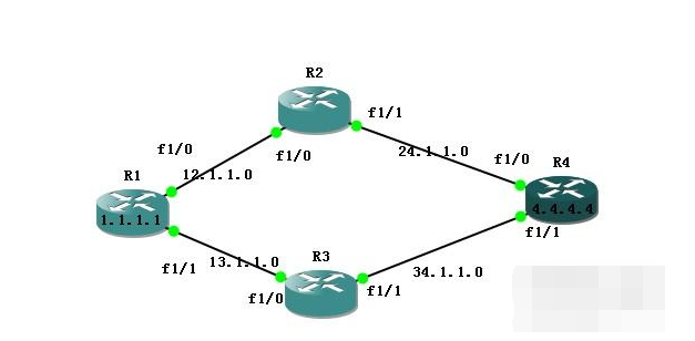
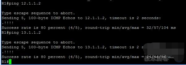
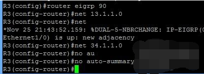
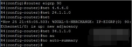
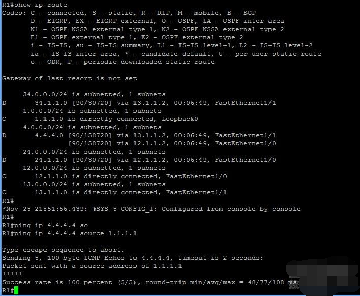
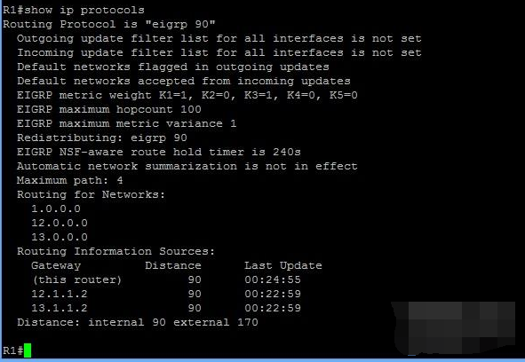
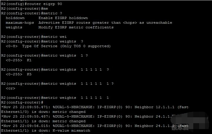
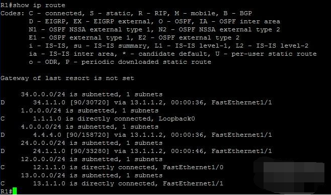
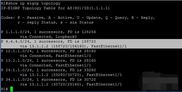
EIGRP selects a primary route (best route) and a backup route on the topology table (EIGRP supports up to 6 links to the destination). It supports several routing types: internal, external (non-EIGRP) and summary routing. EIGRP uses mix. i. Five standards for EIGRP Metric 1. Bandwidth: 10 to the power of 7 divided by the lowest bandwidth between source and destination multiplied by 256 2. Delay: The cumulative delay of the interface is multiplied by 256, in microseconds 3. reliability: The value of the most unreliable reliability between source and destination based on keepalive (the greater the number, the more reliable) 4. Load: The source based on packet rate and interface configuration bandwidth The value of the worst load between the target and the purpose (the worst, the teacher said is the one with the highest number! Remember me) 5. Maximum Transmission Unit (MTU): The smallest MTU.MTU in the path is included in the EIGRP routing update, but generally does not participate in the EIGRP degree operation. Ii. Calculation of EIGRP Metric: EIGRP uses DUAL to determine the best route to the destination. EIGRP does not use when the best route is out of order Holddown timer and immediately use the backup route (feasible successor), which makes EIGRP can quickly converge EIGRP calculation formula, K is a constant, the formula is as follows: Metric=[K1*bandwidth+(K2*bandwidth)/(256–load)+K3*delay]*[K5/(reliability+K4)] Default: K1=1, K2=0, K3=1, K4=0, K5=0 It is not recommended to modify the K value. The K value is carried by the EIGRP hello packet. If the K values ​​of the two routers do not match, they are Metric weight Tos K1 K2 K3 K4 K5 does not form a neighbor relationship to modify the K value, Tos defaults to 0. Bandwidth: The minimum bandwidth of the link between the source and destination, in kbp. Load: The heaviest load of the link between the source and destination, based on the packet rate and the configured bandwidth of the interface. Delay: The cumulative delay of the interface between the source and destination. Reliability: The lowest reliability between source and destination based on the survival message. Maximum Transmission Unit (MTU): The smallest MTU in the path. EIGRP also introduces five K values ​​when calculating the mixed metric: K1 to K5, which correspond to bandwidth, load, delay, reliability, and maximum transmission unit. Note that the K value is only used as a multiplier when calculating, and is not equal to the corresponding real value. For example, the value of K1 is not equal to the value of the bandwidth. By default, EIGRP only considers bandwidth and latency (ie, K1 and K3) when calculating mixed metrics, but can manually modify the K value to control the factors considered. The values ​​of K1 to K5 in the formula can be manually set to any integer between 0 and 255. By default, K1 and K3 are set to 1, and other K values ​​are set to 0. The formula can be simplified to (Bandwidth + Delay) * 256. The K values ​​of all routers in the EIGRP domain must be set to the same value, otherwise routing loops may occur. Cisco stipulates that if two EIGRP routers have different K values, they will not establish a neighbor relationship. Bandwidth for EIGRP = 107 / Interface Bandwidth Delay for EIGRP = Interface Delay / 10 On Cisco routers, bandwidth and latency can be set manually. IGRP also uses the same basic formula to calculate the mixed metric, the only difference being that the formula has no multiplier 256. EIGRP also uses Hops, but hop counts are not included when calculating mixed metrics. On Cisco routers, the default maximum number of hops is 100, and any route with more than 100 hops will be considered unreachable. The experimental topology is as shown above. First, we use the eigrp protocol to do the above topology. R1(config)#int lo 0 R1(config-if)#ip add 1.1.1.1 255.255.255.0 R1(config-if)#no shut R1(config-if)#exit R1(config)# R1(config)#int f1/0 R1(config-if)#ip add 12.1.1.1 255.255.255.0 R1(config-if)#no shut R1(config-if)#exit R1(config)#int f1/1 R1(config-if)#ip add 13.1.1.1 255.255.255.0 R1(config-if)#no shut R2(config)#int f1/0 R2(config-if)#ip add 12.1.1.2 255.255.255.0 R2(config-if)#no shut R2(config-if)#exit R2(config)#int f1/1 R2(config-if)#ip add 24.1.1.1 255.255.255.0 R2(config-if)#no shut R3(config)#int f1/0 R3(config-if)#ip add 13.1.1.2 255.255.255.0 R3(config-if)#no shut R3(config-if)#exit R3(config)# R3(config)#int f1/1 R3(config-if)#ip add 34.1.1.1 255.255.255.0 R3(config-if)#no shut R3(config-if)#exit R4(config)#int lo 0 R4(config-if)#ip add 4.4.4.4 255.255.255.0 R4(config-if)#no shut R4(config-if)#exit R4(config)# R4(config)# int f1/0 R4(config-if)#ip add 24.1.1.2 255.255.255.0 R4(config-if)#no shut R4(config-if)#exit R4(config)# R4(config)#int f1/1 R4(config-if)#ip add 34.1.1.2 255.255.255.0 R4(config-if)#no shut R4(config-if)#exit The IP address is configured successfully. Use the EIGRP protocol to achieve network-wide interconnection R2(config)#router eigrp 90 R2(config-router)#net 12.1.1.0 R2(config-router)#net * Nov 25 21: 43: 32.791:% DUAL-5-NBRCHANGE: IP-EIGRP (0) 90: Neighbor 12.1.1.1 (FastEthernet1 / 0) is up: new adjacency R2(config-router)#net 24.1.1.0 R2(config-router)#no au R2(config-router)#no auto-summary R2(config-router)# Declare routing protocol Successfully learned the entire network routing entry and successfully communicated EIGRP test First we look at the EIGRP neighbor of R1. R1 has two EIGRP neighbors EIGRP uses a variety of parameters to calculate the metric value to the target network, including the bandwidth delay load confidence MTU. The five parameters are identified by the K value. If the K values ​​between the two EIGRP routers are different, the metric is calculated on behalf of both parties. Different ways, so EIGRP neighbor relationships cannot be formed between two routers with different K values. EIGRP metric calculation method When calculating the METRIC value, only the bandwidth in the outbound direction of the interface is calculated, that is, on a link, only the bandwidth of the outbound interface is calculated. Let's take a look at the five K values ​​of the EIGRP router R1. It can be seen that the five K values ​​are 1 0 1 0 0 Verify that the K value is different, the EIGRP neighbor relationship cannot be established, then we modify the K value of the router R2. After modifying the K value of R2, the error message indicates that the K value does not match and the neighbor relationship cannot be established. Try to calculate the metric value from R1 to target 4.4.4.4 First we need to know the minimum bandwidth and the sum of the delays from the link R1 to 4.4.4.4 Minimum bandwidth = minimum bandwidth of the outgoing interface The sum of delays = the sum of the delays of all link outbounds It can be seen that the bandwidth of the Ethernet link is 100000, which is the minimum bandwidth of the entire link. The sum of the delays from the R1 to 4.4.4.4 links is R1 f1/0 + R2 f1/1 + R4 lo0 = 100+100+5000=5200 Put the above values ​​into the metric calculation formula Check whether the value seen in the routing table is the same as the value in the routing table. Same as the value in the routing table, at which point we successfully calculated METRIC Metrics from routers R2 through 4.4.4.4 are calculated in the same way Bandwith=10000 Delay= 100+5000=5100 The final metric is experiment: Modify the bandwidth of the interface of R2 to affect the calculation of metric, and finally affect the routing table. R2(config)#int f1/1 R2(config-if)#bandwidth 50000 At this point we see that there is only one path R1-R3-R4 from R1-4.4.4.4 The next hop to the route to 4.4.4.4 is 13.1.1.2, which is R3. Testing EIGRP protocol for non-equivalent load balancing The FD value of R1 to 4.4.4.4 is 158720 AD value is 156160 We do not see the path of R1-R2-R4 in the EIGRP topology table. The topology table stores successor and fessible successor. If a path does not become a faithful successor, the reason is that the AD value of the path is greater than the FD of the successor. Value, then we will calculate the metric of R2 to 4.4.4.4 now Bandwith=50000 Delay=100+5000 Nested into the formula metric=181760 is greater than the FD value of the successor, so the path will not be placed in the topology table Aluminum Heat Sink,Large Aluminium Heat Sink,Heat Sink Profiles Aluminium,Extruded Heat Sink Profiles Original Electronics Technology (Suzhou) Co., Ltd. , https://www.original-te.com