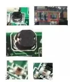
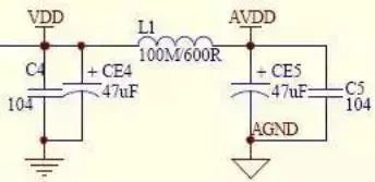
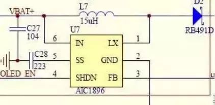
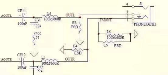
What is the meaning of the current? Oh, this is a temper of the inductance component, it is this cow temper, you can not leave it in many places! Or start by knowing the inductance! The actual structure of the inductor is very simple. Take an enameled wire and wind it into a coil. It is an inductor! Using a magnetic block to make the enameled wire is a magnetic bead. The common ones in mpn are this. Look like this: In the circuit diagram, the inductance is generally expressed by L. Just as the resistor is R and the capacitor is represented by C, you can see which component in the circuit diagram is marked with L next to it and use the symbol: To express the inductance, what needs to be noted here is that with this The symbol is different. This symbol is a kind of resistance. Don't think of it as an inductor! The inductor is not divided into positive and negative poles. In the circuit, you don't need to be connected to which side is connected to the positive side. It is to be phase-divided, that is, the coil of the inductor is wound, and mpn does not need to be considered)! The size of the inductor is made by "Henry", referred to as Hen (H), and the unit smaller than it is millihenry (mH) And Weiheng (uH), they are converted in thousands! What is the temper of the inductor? Why is it giving the current to the opposite? The original inductor is in the circuit when the current is going to pass through it, it will generate a voltage of its own, the current direction of this voltage is just the current and the current to be passed. The opposite direction - the top cow! But this is only a matter of moments, then there is no such resistance! When the current through the inductor in the circuit is to be disconnected, the inductor generates a voltage, the generated current is just The direction of the current to be disconnected is reversed - it does not let the current break! It is topped with a cow, huh, huh, saying that it is not wronged with the current. Upgrade theory: To learn thoroughly about the theory of inductance, we must carefully learn to get through the "Law of the Times"! What is an inductor? Inductors (inductors) and transformers are electromagnetic induction components that are wound with insulated wires (such as enameled wire, yarn wrapped wire, etc.) and are one of the commonly used components in electronic circuits. First, self-inductance and mutual sensation (1) Self-inductance When a current flows through the coil, a magnetic field is generated around the coil. When the current in the coil changes, the surrounding magnetic field also changes accordingly. The changed magnetic field can cause the coil itself to generate an induced electromotive force (the electromotive force is used to indicate the terminal voltage of the ideal power source of the active component), which is self-inductance. (2) Mutual sense When the two inductor coils are close to each other, the change in the magnetic field of one inductor coil will affect the other inductor coil. This effect is mutual inductance. The magnitude of the mutual inductance depends on the degree to which the inductance of the inductor is coupled to the two inductors. Second, the role of the inductor The main function of the inductor is to isolate, filter or form a resonant circuit with capacitors, resistors, etc.; boost, buck is often inseparable from it! Now analyze several inductive circuits and analyze their respective roles in the circuit: Figure 1 Figure 1 is a vcc and avcc power filter circuit in mp3, vcc and avcc voltage are 3v, vcc is for the main control power supply, requires voltage stability and is a pure DC component, does not allow AC components! avcc is given The audio amplifier circuit provides energy, and it needs to have enough DC energy supply! It may be asked, why should the two voltages be connected to an inductor L1 even if it is 3v? The audio amplifier circuit amplifies the sound, along with the high-pitched bass. The small current changes, the required current will vary greatly in magnitude. Although the inductance and capacitance are opposite in temper, but the common point is that the voltage across the inductor and capacitor cannot be abrupt, so the inductor L1 and the capacitors on both sides have a stable vcc and The effect of the avcc voltage, that is, the voltage fluctuation caused by the sound amplification does not affect the fluctuation of the vcc voltage supplied to the main control work; in addition to this effect, there is a second effect by the L1 and the capacitance on both sides, that is, the filtering effect, due to the sound amplification It is easy to mix and enter the AC component in the circuit. This AC component must never enter the vcc voltage and enter the master control. L1 will In order to prevent the main components from entering the AC component, the blocked AC component cannot pass through L1, and it has to disappear through C5 and CE5. The circuit composed of C5 and CE5+L1+C4 and CE4 is also called “π-typeâ€. filter! Figure II Figure 2 is the screen backlight boost circuit in the mp3 circuit. The screen backlight in mp3 is usually connected by 2-3 LED tubes. The LED tube needs 3v DC voltage. Light up, 2 strings need 6v voltage, 3 strings will be 9v voltage can be fully lit! We know that the highest voltage of lithium battery in mp3 is 4.2v, the normal working voltage is only 3.7v, this voltage is fundamental There is no way to light up more than two LED tubes connected in series, so the voltage of 3.7v must be raised to 6v or 9v to illuminate the LED tube! This circuit is such a boost circuit. In the circuit, U7 is a boosting integrated block, which combines with L7, C28, etc. to form a oscillating elevated AC voltage, and then the D2 component (called diode, we will talk about its role in the next lecture) The AC power turns into DC power to illuminate the LED tube! So the L7 inductor here is the boost resonant inductor! Figure III Figure 3 shows that the mp3 headphone circuit has three magnetic bead inductors, L4, L5 and L6. L4 and L5 are used to block the AC component (called ultrasonic wave) that is too fast to be heard in the sound, and let it pass through the capacitor. C31, C32 into the ground, no longer enter the earphones, let us feel the sound is not pure and fatigue! We know that the mp3 radio antenna uses the earphone cable as the antenna, and the role of the magnetic bead inductor of L6 is to block the radio wave signal sent from the earphone cable. Can't let it enter the ground and only enter the antenna receiving pin of the FM radio block! In Figure 3, the 6-pin of U7 is the power input pin, the 5 pin is the unloading, the 4 pin is the working state of the control U7, the high-potential (with voltage) when the working screen backlight is on, the low-potential 0v stops working, the screen background The light is off, the power saving state; 3 feet are output compensation, 2 feet are grounded, and 1 pin is connected to the inductor oscillation output. When the inductance value is constant, the faster the oscillation speed, the faster the current direction changes, and the higher the output voltage! R22 in Figure 3 is the compensation resistor E3, E4, E5 is the electrostatic high-voltage discharge resistor, or Do not pick up!
Wire harness and the surrounding parts shall be even and sufficient distance shall be kept from the heat source,
Considering the protection against electromagnetic interferencee,
Consider assembly technology, maintenance technology,
Grounding wire layout,
Heat dissipation of wire harness and fuse box
Car Seat Harness,Power Seat Wiring Harness,Power Seat Harness,Right Seat Wire Harness Dongguan YAC Electric Co,. LTD. , https://www.yacentercn.com


It’s this kind of temper of inductance that allows us to use it to play a certain role. Think about it. We talked about the alternating current in the circuit that has a changing direction. This exchange is constantly changing. Sometimes we You don't need it. Sometimes we need it. The smart human is naturally thinking of the temper of using the inductor. The direction of the alternating current is constantly changing, and the inductance is constantly resisting. As a result, the alternating current in the direction cannot pass the inductor. Since the direct current does not change in the direction of the current, the current can pass through the inductor smoothly. The magnitude of the inductance is not the same as that of the fast change of the alternating current. The same inductor blocks the fast changing current and blocks the alternating alternating current. Small; for the same change speed of AC, the sense of large value is large, and the small value of the sense is small! Oh, we can easily separate the AC and DC in the circuit by using the character of the inductor! Everyone may think of a capacitor here. The characteristic of the capacitor is "DC, DC ", Then the characteristics of the inductor is just and capacitor opposite:! Every exchange, through the DC circuit, precisely because of inductance and organic complexes capacitance, only to circuits AC and DC easily are off course, the characteristics of the inductor also There are some other functions, these need you to upgrade and learn, and slowly understand! 

