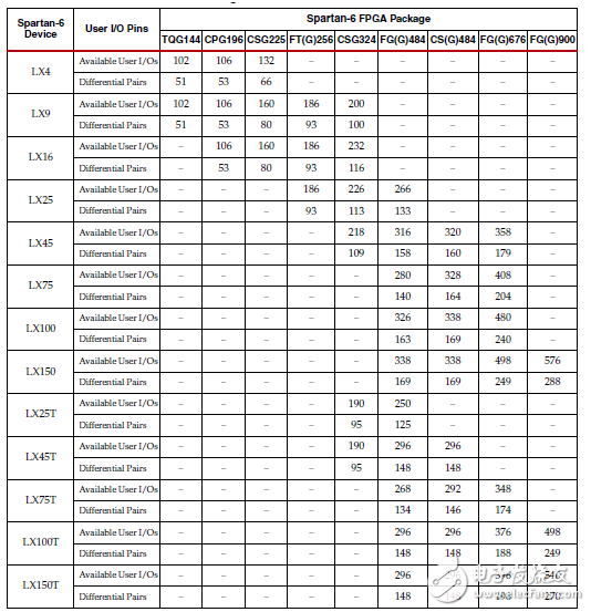
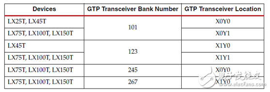
1. Spartan-6 series package overview Table 1: Spartan-6 series FPGA package 2. Spartan-6 series pin assignment and function details Dedicated configuration pins, shown in Table 2, GTP high-speed serial transceiver pins, shown in Table 3 Table 2: Spartan-6 FPGA dedicated configuration pins Note: Only LX75, LX75T, LX100, LX100T, LX150, and LX150T devices have VFS, VBATT, and RFUSE pins. Table 3: Number of GTP channels in Spartan-6 devices Note: LX75T encapsulates 4 GTP channels in FG(G)484 and CS(G)484, and 8 GTP channels in FG(G)676; LX100T encapsulates FG(G)484 and CS(G)484 4 GTP channels are encapsulated in FG(G)676 and FG(G)900, while 8 GTP channels are encapsulated in FG(G)676 and FG(G)900. As shown in Table 4, the number of available IO pins for each type and package of the device is not the same. For example, for the LX4 TQG144 device, it has a total of 144 pins, of which IO can be used as a single-ended IO pin. The number is 102. These 102 single-ended pins can be used as 51 pairs of differential IO, and the other 32 pins are power supplies or special functions such as configuration pins. Table 4: Summary of available IO resources in Spartan6 series packages Table 5: Pin function details 3. Spartan-6 series GTP Transceiver pin As shown in Table 6, for LX25T and LX45T, there is only one GTP Transceiver channel, its location is X0Y0, and the bank number is 101; the interpretation of other signals GTP Transceiver is similar. Table 6: Bank code of GTP Transceiver
Anisotropic magnets are magnets whose magnetization directions in the magnets are aligned in a certain direction.
Magnet powder for anisotropic magnets is composed of a single crystal or polycrystal with an aligned direction of magnetization in one magnet particle. When a magnetic field is applied externally during molding (this magnetic field is called an aligning magnetic field), the magnet powder moves to align with the direction of the magnetic field and is solidified in an aligned state, resulting in an anisotropic magnet. Magnet powder aligned with an aligning magnetic field is solidified with keeping magnetization. Therefore, after removing the alignment magnetic field, the molded body becomes a magnet having a magnetic force. Anisotropic Ferrite Magnets,Pump Magnet,Cooler Pump Magnet,Submersible Pump Magnet HU NAN YUBANG MAGNETIC MATERIAL CO.,LTD , https://www.ybmagnet.com
The Spartan-6 series has a low-cost, space-saving package that can maximize user pin density. The pin assignments between all Spartan-6 LX devices are compatible, and the pin assignments between all Spartan-6 LXT devices are compatible, but the pin assignments between Spartan-6 LX and Spartan-6 LXT devices are Incompatible. 
The Spartan-6 series has its own dedicated pins. These pins cannot be used as Select IO. These dedicated pins include: 


Pin name direction description User I/O Pins IO_LXXY_# Input/
Output IO indicates that this is a pin with input and output functions, XX indicates the unique identification of the pin in its Bank, and Y indicates whether it is a P or N pin of a differential pin MulTI-FuncTIon Pins IO_LXXY_ZZZ_# Zzz represents other functions of this pin besides IO function, Dn Input/
Output
(during readback) In SelectMAP/BPI mode, D0—D15 are data pins for configuration operations. In the readback phase from SelectMAP, when RDWR_B is low, Dn is the output pin. After the configuration process is over, this pin Can be used as a general IO port D0_DIN_MISO_MISO1 Input In Bit-serial mode, DIN is the only data input pin;
In SPI mode, MISO is the master input and slave output pin;
In SPI x2 or x4 mode, MISO1 is the second data line of the SPI bus; D1_MISO2,
D2_MISO3 Input In SelectMAP/BPI mode, D1 and D2 are the low 2bits of the configuration data line; in SPIx4 mode, MISO2 and MISO3 are the high 2bits of the SPI bus data line An Output In BPI mode, A0-A25 are output address lines, after configuration, they can be used as ordinary IO AWAKE Output State output pin in suspend mode. If suspend mode is not enabled, this pin can be used as a normal IO pin MOSI_CSI_B_MISO0 Input/
Output Master output and slave input pin in SPI configuration mode;
In SelectMAP mode, CSI_B is a low effective Flash chip select signal;
In SPI x2 or x4 mode, this is the lowest data line FCS_B Output In BPI mode, the chip select signal of BPI flash FOE_B Output In BPI mode, the output of BPI flash is enabled FWE_B Output In BPI mode, BPI flash write enable LDC Output In BPI mode, LDC remains low during the configuration phase HDC Output In BPI mode, HDC remains low during the configuration phase CSO_B Output In SelectMAP/BPI mode, daisy chain chip select signal;
In SPI mode, it is the chip select signal of SPI Flash; IRDY1/2,
TRDY1/2 Output When using PCI IP Core, they are used as IRDY and TRDY signals DOUT_BUSY Output In SelectMAP mode, BUSY represents the device status;
In Bit-serial mode, DOUT outputs data to devices downstream of the daisy chain RDWR_B_VREF Input In SelectMAP mode, RDWR_B is a low-effective write enable signal; after configuration, it can be used as normal IO HSWAPEN Input When it is low, pull up all IOs before configuration INIT_B BidirecTIonal
(open-drain) Low level indicates that the configuration memory is empty; when it is pulled low, the configuration will be delayed; if it becomes low during the configuration process, it indicates that an error occurred during the configuration process; when the configuration is over, this pin indicates a POST_CRC error ï¼› SCPn Input SCP0-SCP7 are suspend control pins CMPMOSI,
CMPMISO,
CMPCLK N/A Reserved for future use, can be used as ordinary IO M0, M1 Input Configuration mode, M0=0 means parallel configuration mode, M0=1 means serial configuration mode; M1=0 means master mode, M1=1 means slave mode CCLK Input/
Output Configure clock, output clock in master mode, input clock in slave mode USERCCLK Input Optional user input configuration clock in master mode GCLK Input Global clock pins, they can be used as ordinary IO VREF_# N/A Reference threshold clock pin, can be used as ordinary IO when not in use MulTI-Function Memory Controller Pins M#DQn Input/
Output #Bank's storage controller data line M#LDQS Input/
Output #Bank's memory controller data enable pin M#LDQSN Input/
Output #Bank's memory controller data enable pin N M#UDQS Input/
Output #Bank's memory controller high data enable M#UDQSN Input/
Output #Bank's storage controller high data enable N M#An Output #Bank's storage controller address line A[0:14] M#BAn Output #Bank's memory controller block address line BA[0:2] M#LDM Output #Bank's memory controller low data shield M#UDM Output #Bank's storage controller high data shielding M#CLK Output #Bank's memory controller clock M#CLKN Output #Bank's memory controller clock N M#CASN Output #Bank's memory controller column address enable M#RASN Output #Bank's memory controller row address enable M#ODT Output #Bank's storage controller terminal resistance control M#WE Output #Bank's storage controller write enable M#CKE Output #Bank's memory controller clock enable M#RESET Output #Bank's memory controller reset Dedicated Pins DONE_2 Input/
Output A bidirectional signal with an optional pull-up resistor. As an output, it represents the completion of the configuration process; as an input, it can be pulled down to delay the start PROGRAM_B_2 Input Asynchronous reset configuration logic SUSPEND Input High level makes the chip enter suspend mode TCK Input JTAG boundary scan clock TDI Input JTAG boundary scan data input TDO Output JTAG boundary scan data output TMS Input JTAG boundary scan mode Reserved Pins NC N/A Pin not connected CMPCS_B_2 Input Reserved pin, not connected or connected to VCCO_2 Other Pins GND N/A Ground VBATT N/A Only exists in LX75, LX75T, LX100, LX100T, LX150 and LX150T chips, to decode key memory backup power; if key memory is not used, it can be connected to VCCAUX, GND or not directly connected VCCAUX N/A Power supply for auxiliary circuit VCCINT N/A Internal core logic resources VCCO_# N/A #Bank's output driver power supply VFS Input Only exists in LX75, LX75T, LX100, LX100T, LX150, and LX150T chips; the power supply used in the decoder key EFUSE programming process, if the key fuse is not used, connect this pin to VCCAUX, GND or leave it alone RFUSE Input Only exists in LX75, LX75T, LX100, LX100T, LX150 and LX150T; the decoder key EFUSE resistor used for programming, if you do not program or use key EFUSE, connect this pin to VCCAUX, GND or leave it alone Pin name direction description GTP Transceiver Pins MGTAVCC N/A Transceiver hybrid circuit power supply MGTAVTTTX,
MGTAVTTRX N/A TX, RX circuit power supply MGTAVTTRCAL N/A Power supply for resistance calibration circuit MGTAVCCPLL0
MGTAVCCPLL1 N/A PLL power supply MGTREFCLK0/1P Input Positive reference clock MGTREFCLK0/1N Input Negative reference clock MGTRREF Input Precision reference resistance of internal calibration circuit MGTRXP[0:1] Input Transceiver receiver positive MGTRXN[0:1] Input Transceiver receiver negative MGTTXP[0:1] Output Transceiver transmitter positive MGTTXN[0:1] Output Transceiver transmitting terminal negative 