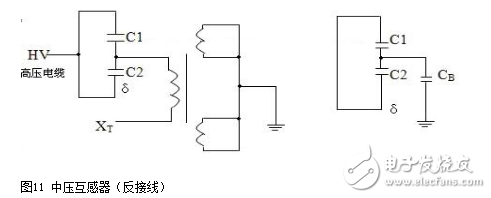
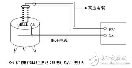
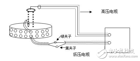
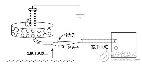
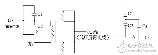
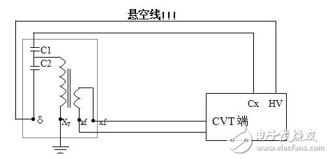
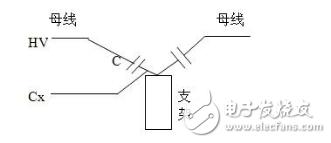
The dielectric loss insulation test can effectively find the overall moisture deterioration and deterioration of electrical equipment insulation, as well as local defects, etc., and is widely used in electrical manufacturing, electrical equipment installation, handover and preventive tests. The anti-interference dielectric loss tester adopts the variable frequency power supply technology, and uses the single chip microcomputer and electronic technology to perform automatic frequency conversion, analog/digital conversion and data calculation, and achieves the functions of strong anti-interference ability, fast test speed, high precision and easy operation. The variable frequency power supply adopts high-power switching power supply, output 45Hz and 55Hz pure sine wave, automatic pressure, can provide voltage up to 10kV; automatically filter out 50Hz interference, suitable for field test of large electromagnetic interference such as substation. 1. Self-excited test with CVT, one-time wiring, simultaneous measurement of C1, C2 capacitance and tgδ. 2. It has the external application voltage and the measurement function of the external CN. 3, the instrument measurement accuracy is high, can meet the oil dielectric loss measurement requirements, so only need to equip the standard oil cup, and the special test line can achieve oil dielectric loss measurement. 4, using frequency conversion technology to eliminate on-site 50Hz power frequency interference, even in the environment of strong electromagnetic interference can also measure reliable data. 5. Grounding protection function. When the instrument is not grounded or the grounding is poor, the instrument does not enter the normal program and does not output high voltage. 6. Over-current protection function, the instrument is not damaged when the sample is short-circuited or broken down. 7. Standard capacitor and high voltage power supply are included to facilitate on-site testing and reduce field wiring. 8, the instrument uses a large-screen LCD display, the test process through the Chinese menu prompts are both intuitive and easy to operate. 1, measurement range: capacitance value: 4 ~ 60000pF Dielectric loss value: 0 ~ 100% 2, the maximum error: capacitance accuracy: ± (1.0% × reading ± 1pF) Dielectric loss accuracy: ± (1.0% × reading ± 0.04%) 3. Resolution: Capacitance resolution: minimum resolution 0.001pF Dielectric loss resolution: minimum resolution 0.001% 4, high voltage output: 0.5 ~ 10kV45Hz and 55Hz, current output ≤ 200mA 5, low voltage output: output voltage 3 ~ 50V output current 3 ~ 30A 6, power supply: AC220V ± 10%, 50Hz or generator power supply 7, working environment: ambient temperature: 0 ~ 40 ° C; Ambient humidity: ≤90% RH, no condensation 8, the external dimensions: 400 × 315 × 350mm2 9, weight: 20kg Instrument lead terminal description: HV---The high-voltage end of the measuring lead of the instrument (with dangerous voltage). CX---Test current input terminal when wiring. --- The grounding end of the instrument is connected to the earth reliably when in use. When the low voltage measuring end of the device under test is insulated from the ground, it can be measured by this wiring method. (1) The high voltage shielding wire is connected to the high voltage end of the tested equipment; The black special low-voltage cable is taken out from the Cx end of the instrument panel, and the low-voltage core wire is connected to the low-voltage end L of the device under test (see Figure 11); the low-voltage shielded wire is connected to the shielded end E of the tested device. (The sample is unshielded and is suspended) Do not short-circuit the core wire and shield wire of HVx and Cx. Otherwise, it cannot be sampled and cannot be measured. Figure 4 shows the standard wiring method for the standard capacitor BR16, which is the positive wiring method. Figure 5 shows the reverse wiring method, and the one end of the standard capacitor BR16 is forcibly grounded. Note: The HV jack outputs a dangerous voltage of 10kV, and the high-voltage insulated cable is plugged into the HV jack. Figure 6 standard capacitor positive wiring BR26 or standard dielectric loss device DB-100, etc. (non-grounded test) wiring method Figure 7 Standard capacitor BR26 or standard dielectric loss device DB-100 and other reverse wiring (grounding test) wiring method 1) Conventional method: using the positive connection method, as shown in Figure 8: Figure 8 conventional wiring method The X grounding point is opened, so that A and X are connected to the HV end of the instrument, and all the windings of the low voltage end are shorted and then connected to the Cx terminal. Note: This test voltage is 2 ~ 3kV, and the high voltage A, X short circuit should pay attention to the X end lead and the terminal box to maintain the distance. 2) End shielding method (positive wiring method), see Figure 9, can apply 10kV voltage, the capacitance value is much smaller than the conventional method due to the unequal voltage distribution of the voltage in the AX winding. Figure 9 end shielded wiring 3) The end pressurization method (positive wiring method) is shown in Fig. 10. This method is limited by the X-point withstand voltage and can only apply 2.5 to 3 kV voltage. Similarly, the capacitance value error is large. Figure 10 terminal pressurization wiring 1) Method for measuring medium voltage transformer tgδ As shown in Figure 11, the C2 terminal δ is connected to the C1 head end by the reverse wiring method, and the instrument HV port (using the high voltage cable) XT is suspended, and the medium voltage transformer secondary coil is short-circuited to the ground. Since C1+C2 is much larger than CB, tgδ≈tgδB measured by this method. If the on-site CB value is small, the field interference is large, and the data error measured by the reverse wiring may be large. At this time, the positive wiring method can be selected. First disconnect all the secondary leads of the CVT, short-circuit the secondary coil, and then connect to the CX measurement line of the instrument. XT is suspended. The wiring method is shown in Figure 12: Figure 12 pressure transformer (positive wiring) 2) Measurement of capacitance C1 and tgδ1, C2 and tgδ2: The wiring for measuring the main capacitances tgδ1 and C1 is as shown in FIG. Excited and pressurized by the intermediate transformer, the XT point is grounded. The high voltage end of the main capacitor C1 is connected to the CX end of the instrument by the CX line, and the δ end of the voltage dividing capacitor C2 is connected to the HV high voltage end of the instrument by another CX line. Due to the "δ" end insulation level, the test voltage does not exceed 3kV. Figure 13 Wiring of capacitors C1 and tgδ1, C2 and tgδ2 After the wiring is completed, select the measurement method to the CVT, and the test voltage should not exceed 3.0kV. The instrument automatically tests, and the capacitance and dielectric loss of C1 and C2 are automatically or manually printed after the test is completed. Press “Enlarge†and “Reduce†to display the page to display the capacitance and dielectric loss of C1 and C2. 1) For a separate bushing (not installed in the transformer), measure the capacitance and dielectric loss value of the conductive rod to the measuring screen. The high voltage terminal HV is connected with the conductive rod, and the CX is connected to the measuring screen, and the measurement is performed by the positive wiring method. 2) For the bushing mounted on the transformer, due to the connection between the conductive rod and the winding, the conductive rods of the A, B, C, and O bushings must be short-circuited to the high voltage end of the HV, and the Cx end is connected to the measuring screen of the different bushings. The positive wiring method measures capacitance and dielectric loss values. The outer casing of the transformer is directly grounded, so the instrument is measured by reverse wiring. The measurement site is performed as shown in the following table. Note: The high voltage is led out by the HV jack, one end of the high voltage cable is inserted into the HV jack, and the other end is connected to the high voltage end of the coil under test. The Cx jack is not used. Measuring coil and grounding Serial number double coil transformer three coil transformer Grounded part of the coil to be tested 1 low pressure housing and high voltage coil low voltage housing, high voltage and medium voltage coil 2 high pressure housing and low voltage coil medium voltage housing, high voltage and low voltage coil 3 high pressure housing, medium voltage and low voltage coil 4 high and low pressure housing high and medium voltage housing and low voltage coil 5 high pressure, medium pressure and low pressure housing When measuring the dielectric loss and capacitance of the fracture capacitor, add the high voltage cable and the Cx measurement cable to both ends of the fracture capacitor and measure with positive wiring. As shown in Figure 14: Figure 14 Circuit breaker fracture capacitance test wiring 1) Current transformers with chain or cascade structure: On-site measurement of such current transformers can be measured by positive connection of the secondary winding once, or by grounding all secondary windings by reverse wiring. 2) Capacitive current transformer: The outermost layer has the end of the last screen. During the test, the positive connection can be used to measure the tgδ and capacitance of the primary winding relative to the final screen. 1) When windy weather occurs at the test site, it is necessary to support the insulation rod and avoid the poor connection of the high voltage end, resulting in unstable test data, incorrect or instrument reset. 2) The metal body of the high voltage cable HV socket has a dangerous high voltage of 10kV. Electric Water Heater,Home Electric Water Heater,Wall Mounted Air Source Water Heater,Homely Electric Water Heater Shandong Sangle Group Co.,Ltd. , https://www.sangle-group.com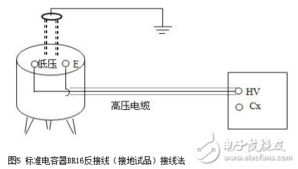


Which dielectric loss tester is good _ anti-interference dielectric loss tester
MS-101D anti-interference dielectric loss tester I. Overview