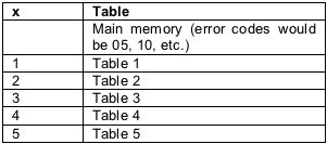
Any line starting with ";" is a comment and can be ignored. The user can use the table not used for programming as a comment. The main device and Table 1 are annotated in the template file. When setting up the table, do not comment the table markers and register programming lines (ie, remove the ";" symbol at the beginning of the line). The analysis program finds that there is no comment mark, and the text starts with the table number, confirming the start of a table. For example, when setting up Table 3, start by marking Table 3 (see Figure 2). After the table indicator, the analysis program starts looking for the special format data of the device internal setting table. As the template shows, the data should have the following format: The analysis program only pays attention to the address and data to determine whether the data conforms to the limits of a certain table. If the analysis program determines that the data does not meet the requirements of the table, it will report an error. When the analysis program finds a non-data symbol or carriage return, it is considered that the setting of a certain table has been completed. Then, the analysis program starts looking for the beginning of a new table (corresponding to the indicator of the table), or the end of the file, and returns control to the main program. In the status window, the program reports the work that has been completed, and the work should be checked to confirm that no errors have occurred. Figure 3 shows the error code and the corresponding error. * Note that the x in the error code represents an actual table. Figure 4 lists the different tables and the corresponding x values. In the lookup table, even if only one value is modified, the user must set the entire table. Special bytes can be set for other configuration tables. The order of the DS1856 table is different and is explained in the data sheet. The program generates a separate text file for the DS1856 and sets the table.
Innosilicon Asic Miner:Innosilicon A9 ZMaster,Innosilicon A9++ ZMaster,Innosilicon A9+ ZMaster
Innosilicon is a worldwide one-stop provider of high-speed mixed signal IPs and ASIC customization with leading market shares in Asian-Pacific market for 10 consecutive years. Its IP has enabled billions of SoC's to enter mass production, covering nodes from 180nm to 5nm across the world`s foundries including: GlobalFoundries, TSMC, Samsung, SMIC, UMC and others. Backed by its 14 years of technical expertise in developing cutting-edge IPs and ASIC products, Innosilicon has assisted our valued partners including AMD, Microchip and Microsoft to name but a few, in realizing their product goals.
Innosilicon team is fully devoted to providing the world's most advanced IP and ASIC technologies, and has achieved stellar results. In 2018, Innosilicon was the first in the world to reach mass production of the performance-leading GDDR6 interface in our cryptographic GPU product. In 2019, Innosilicon announced the availability of the HDMI v2.1 IP supporting 4K/8K displays as well as our 32Gbps SerDes PHY. In 2020, we launched the INNOLINK Chiplet which allows massive amounts of low-latency data to pass seamlessly between smaller chips as if they were all on the same bus. With a wide range of performance leading IP in multiple FinFET processes and 22nm planar processes all entering mass production, Innosilicon's remarkable innovation capabilities have been proven in fields such as: high-performance computing, high-bandwidth memory, encrypted computing, AI cloud computing, and low-power IoT.
innosilicon zec miner,Innosilicon A9 ZMaster,innosilicon a9 50ksol miner,innosilicon a9 miner,a9 50ksol zmaster Shenzhen YLHM Technology Co., Ltd. , https://www.hkcryptominer.com
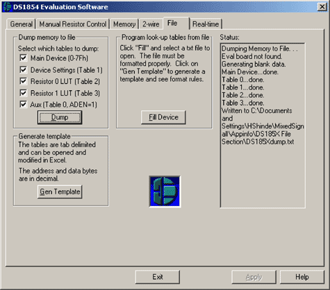
File column in the DS185XEVKIT software. Figure 1 shows the file column of the DS185x evaluation board (DS185XEVKIT) software. You can use the Gen Template and Fill Device buttons to set the device. The Gen Template button first generates a template for importing tables in Microsoft Excel or other formats. Using the Fill Device button, you can modify, save, or update the imported file. 
Figure 1. The file field in the DS185XEVKIT software 
Figure 2. Markers that may appear in the template file address data Annotation field 
Figure 3. When the input data does not meet the template parameters, the error code and the corresponding error 
Figure 4. Table corresponding to the value x
Use the file field of DS185XEVKIT software for device programming
Abstract: Using the DS185x evaluation board (DS185XEVKIT) and related software, the DS185x series devices can be programmed via the I²C serial interface. DS185x devices have an internal EEPROM for device setup and are configured as general-purpose memory or calibration look-up tables. To simplify the lookup table setup, the file column in the software can upload a text file with correct format to the memory. This application note explains the format of the lookup table and what you need to pay attention to when using the DS185XEVKIT software.