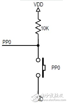
Introduction This application note describes the operation and use of a bootloader program written for the family of S12 and S12X microcontrollers based on 180nm technology. This bootloader makes it easy to implement in-production programming or "in-system" programming, especially for applications where the HCS12 background debug interface (BDM) cannot be used. The user must pre-program the bootloader into S12(X) during the production preparation phase or at the programming vendor. The bootloader will remain in the MCU for future use. This bootloader implementation supports downloading user software into the MCU flash memory via the SCI serial port. The bootloader described in this document is only an example and we are not responsible for any consequences arising out of it, and we do not provide technical support. Hardware compatibility There are two versions of the bootloader: The first one was written for the S12 series (S12P, S12HY, S12HA and S12G). The second is written for the S12X series (S12XS, S12XE and S12XF). Unless otherwise noted, the contents of this application note apply to all two versions. This bootloader is not optimized for the smallest device. Therefore, the MC9S12GN16 is not supported. Programming of D-Flash or EEPROM is currently not supported. demand In order to successfully run this bootloader, you need to meet some requirements. Input pin There are many ways to determine if you want to start the bootloader or the user application. For example, you can choose to determine the state of the input pin, the state of a variable in the EEPROM memory, or the command received from the communication interface. This bootloader uses the first method. After reset, the bootloader will enable the pull-up register of the PP0 pin and read the status of the PP0 pin to determine if you want to run the bootloader. Perhaps the external circuit for this pin is this: a switch, jumper or a button with an optional pull-up resistor. Figure 1. Pin Connection Serial interface All S12(X) microcontrollers have an integrated serial communication interface. Note that an RS232 level shifter is required to communicate with the PC. By default, serial communication will be set to this format: 8 data bits 1 start bit 1 stop bit 0 check digit Xon/Xoff flow control The default baud rate is 9600. It can be modified to 38400, 57600 or 115200 bps in the bootloader menu. Terminal simulator You can use the serial debugging assistant to communicate with the PC. This serial debugger must support serial COM port communication, Xon/Xoff flow control, and support for sending text files. Oscillator The S12 microcontroller does not require an external crystal. The bootloader uses a 1MHz RC oscillator circuit inside the S12 microcontroller. The bootloader sets the bus frequency to 25MHz to support high rate communication. The S12X microcontroller requires a crystal or an external oscillator. Configure the PLL in the bootloader to achieve a 40MHz bus clock frequency. This is to increase the communication rate to speed up the code download. Functional description The bootloader works in a straightforward manner. This section describes only the most important and special ones. Operation GALOCE Force Washer Transducers are miniature load cells designed specifically for measuring fastener clamping forces. The design provides high stiffness in a small package, making these load cells ideal for static and dynamic measurements on fasteners, or structural test applications where space limitations exist. Force washer transducers come in a variety of English and Metric sizes, by the way, GALOCE OEM&ODM group can customized the Load Cell according the drawing. Force Washer Load Cell,Force Washer Transducers,Washer Typer Load Cell,Through-hole force sensor GALOCE (XI'AN) M&C TECHNOLOGY CO., LTD. , https://www.galoce-meas.com