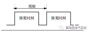
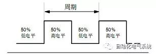
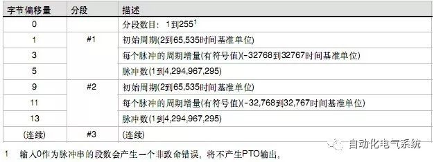
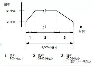
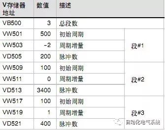
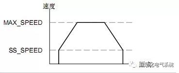
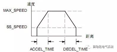
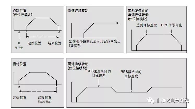
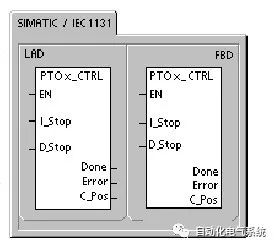
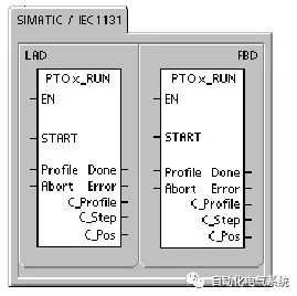
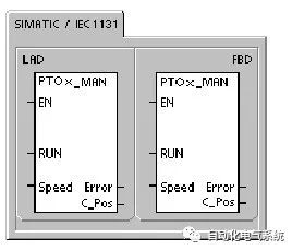
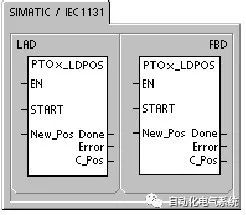
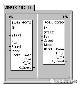
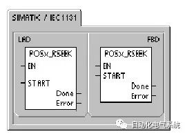
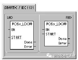
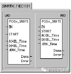
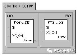
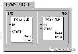
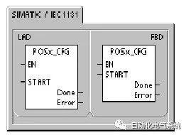
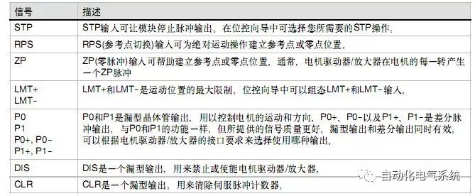
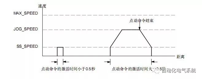
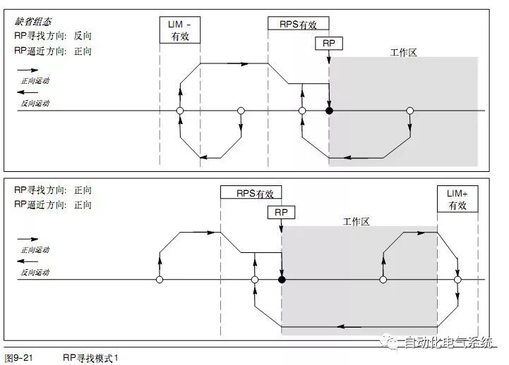
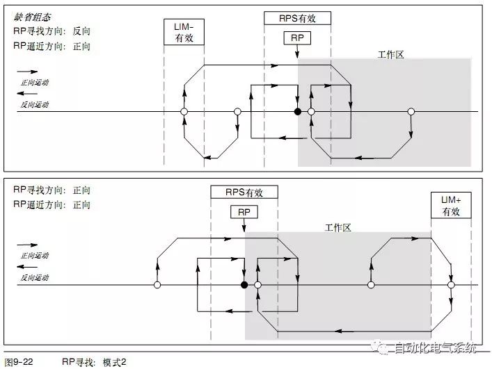
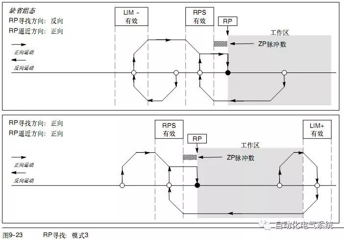
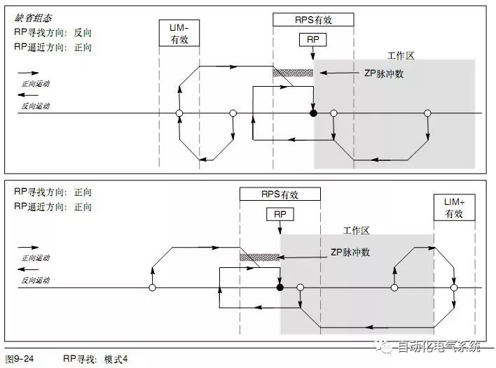
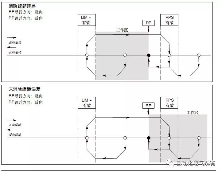
Basic instruction part: Pulse output command (PLS) is used to control pulse train output (PTO) and pulse width modulation (PWM) functions on high-speed outputs (Q0.0 and Q0.1). 1. PWM wave PWM produces a pulse output with a fixed duty cycle change period. The period and pulse width can be specified in microseconds or milliseconds: Period: 10 µs to 65,535 µs or 2ms to 65,535 ms Pulse width time: 0 µs to 65,535 µs or 0ms to 65,535 ms Note: Pulse width ≥ period value and duty cycle is 100%: continuous output is turned on. Pulse width=0 and duty cycle is 0%: the output is turned off continuously. cycle 1.1 There are two ways to change the characteristics of the PWM signal waveform: (1) Synchronous update: If you do not need to change the time base, you can use synchronous update. With synchronous update, the change in signal waveform characteristics occurs on the edge of the cycle, providing smooth transitions. (2) Asynchronous update: Generally, for PWM operation, the pulse width changes when the period remains unchanged, so it is not required to change the time base. However, if you need to change the time base of the PTO/PWM generator, you must use asynchronous updates. Asynchronous update will cause the PTO/PWM function to be instantly disabled, which is not synchronized with the PWM signal waveform. This can cause vibration of the controlled device. For this reason, it is recommended to use PWM synchronous update. Choose a time base that is suitable for all cycle times. 1.2 Features: Period and pulse width are all based on time, especially pulse width is not fixed 0-255 or 0-512 2. Pulse train operation (PTO) TO outputs a series of square waves (duty ratio 50%) according to the given number of pulses and period. PTO can generate single-segment pulse trains or multi-segment pulse trains (using pulse waveforms). You can specify the number of pulses and period (in microseconds or milliseconds as the increment): Number of pulses: 1 to 4,294,967,295 Period: 10 µs to 65,535 µs or 2ms to 65,535 ms. cycle Number of pulses = 0 The number of pulses is set to 1 pulse by default The PTO function allows pulse trains to be "chained" or "queued". When the current pulse train output is completed, a new pulse train will be output immediately. This ensures continuity between multiple output pulse trains. 2.1 Single-stage pipeline of PTO pulse train In single-segment pipeline mode, special registers need to be updated for the next burst. Once the initial PTO segment is started, the special register must be changed according to the requirements of the second signal waveform, and the PLS instruction must be executed again. The attributes of the second burst remain in the pipeline until the transmission of the first burst is completed. Only one burst of attributes can be stored in the pipeline at a time. When the first pulse train is sent, the second signal waveform is output, and the pipeline can be used for the next new pulse train. Repeat this process to set the characteristics of the next burst again. Except for the following two cases, smooth transitions between pulse trains can be made: the time base has changed or the pulse train started has been completed before the new pulse is captured by the PLS instruction. Features: It can output multiple single-ended pulses without stopping in the middle 2.2 Multi-section pipeline of PTO pulse train In the multi-stage pipeline mode, the CPU automatically reads the characteristics of each pulse train from the envelope table in the V memory area. In this mode, only the control byte and status byte of the special memory area are used. To select multi-segment operation, the starting address offset of the profile table in the V memory (SMW168 or SMW178) must be loaded. The time base can be microseconds or milliseconds. However, all period values ​​in the envelope table must use the same time base and cannot be changed while the envelope is running. Execute PLS instruction to start multi-stage operation. The length of each record is 8 bytes, which is composed of 16-bit period value, 16-bit period increment value and 32-bit pulse value. The format of the envelope table is given in the table. You can increase or decrease the pulse period automatically by programming. Entering a positive value in the period increment will increase the period; entering a negative value will decrease the period; entering 0 will not change the period. 2.3 Calculate the value of the envelope table 2.3.1 The multi-stage pipeline function of the PTO generator is very useful in many applications, especially in stepper motor control. For example: You can use a PTO with a pulse envelope to control a stepper motor to achieve a simple acceleration, uniform speed, and deceleration process or a complex process consisting of up to 255 pulse waveforms, and each waveform is It is acceleration, constant speed or deceleration operation. The envelope table values ​​given in the example in the figure require generating an output signal waveform including three segments: stepper motor acceleration (first segment); stepper motor uniform speed (second segment) and stepper motor deceleration (third segment) . For this example: the start and final pulse frequency is 2kHz, the maximum pulse frequency is 10kHz, and 4000 pulses are required to achieve the desired number of motor revolutions. Since the value in the envelope table is expressed in period, not frequency, it is necessary to convert the given frequency value into a period value. Therefore, the start (initial) and final (end) cycle time is 500 µs, and the cycle time corresponding to the maximum frequency is 100 µs. In the acceleration part of the output envelope, it is required to reach the maximum pulse frequency around 200 pulses. It is also assumed that the deceleration part of the envelope is completed in 400 pulses. Period increment of a given segment of De=|ECT--ICT|/Q Among them: End_CTseg = the end period of this segment Init_CTseg = the initial period of this segment Quantityseg = the number of pulses in this segment Using this formula, Segment 1 (Acceleration): Incremental period =-2 Section 2 (constant speed): increment period =0 Section 3 (Deceleration): Incremental period =1 Assuming that the envelope table is stored in the V memory area starting from VB500, the table gives the values ​​that generate the required signal waveform. The value of this table can be placed in the V memory with instructions in the user program. One way is to define the value of the envelope table in the data block. The period of the last pulse of the segment is not directly specified in the envelope, but must be calculated (unless the period increment is 0). If smooth transitions between segments are required, it is useful to know the period of the last pulse of the segment. The formula for calculating the last pulse period of the segment is: The cycle time of the last pulse of the segment=ICT+(DEL*(Q--1)) Among them: Init_CTseg = initialization period of this segment Deltaseg=Delta cycle time of this segment Quantityseg=The number of pulses in the segment Note: The cycle increment can only be specified in microseconds or milliseconds, and the cycle modification is performed on each pulse 2.3.2. The length of time to complete a given waveform segment can be calculated according to the following formula: The duration of the waveform segment=Q*(ICT+((DEL/2)*(Q--1))) Among them: Quantityseg = the number of pulses in the segment ICT=The initialization cycle time of this segment DEL=Incremental cycle time of the segment Features of PTO: The frequency change value in each segment changes once per pulse, and the curve is more uniform and smooth. It can fit complex curves well. Open loop motion control part: 1. S7-200 provides three methods of open loop motion control: Pulse Width Modulation (PWM)-Built in S7-200, used for speed, position or duty cycle control. Pulse train output (PTO) - Built in S7-200, used for speed and position control. EM253 position control module - an additional module for speed and position control. S7-200 provides two digital outputs (Q0.0 and Q0.1), which can be configured as PWM or PTO output through the position control wizard. The position control wizard can also be used to configure the EM253 position control module. When configuring an output for PWM operation, the output period is fixed, and the pulse width or pulse duty cycle is controlled by your program. The change of pulse width can control the speed or position in your program. The EM253 position control module provides a single pulse output with direction control, prohibition and clear output. In addition, dedicated inputs allow the module to be configured in several operating modes including automatic reference point search. The module provides a unified solution for the speed and position open loop control of stepper motors or servo motors. In order to simplify the use of the position control function in your application, the position control wizard provided by STEP 7--Micro/WIN can complete the configuration of PWM, PTO or position control module in a few minutes. The wizard can generate position control instructions, which can be used to dynamically control speed and position in the application. For the position control module, STEP 7--Micro/WIN also provides a control panel that can control, monitor, and test your motion operations. 1.1 Use PWM (Pulse Width Modulation) output PWM produces a pulse output with a fixed duty cycle change period. After starting at the specified frequency (period), the PWM output continues. The pulse width changes according to the required control requirements. The duty cycle can be expressed as a percentage of the period or a time value corresponding to the pulse width. The pulse width can be varied from 0% (no pulse, always low) to 100% (no pulse, always high). Since the PWM output can vary from 0% to 100%, in many cases, it can provide a digital output similar to an analog output. For example, the PWM output can be used to control the motor from stop to maximum speed, or to control the position value of a valve from closed to fully open. 1.2 Basic information of open loop position control for stepper motors or servo motors Both the PTO and EM253 position control modules built in S7-200 PLC use a pulse train output for speed and position control of stepper motors or servo motors. Using PTO or modules for open-loop position control requires expertise in the field of motion control. Provide basic information to help you use the position control wizard to configure PTO or module for your application, Maximum speed and start/stop speed The wizard will prompt you the maximum speed (MAX_SPEED) and start/stop speed (SS_SPEED) of the application. As shown Enter acceleration and deceleration time 1.3 Select the operating mode of the envelope You need to configure the envelope according to the operating mode. PTO supports relative position and continuous rotation at a single speed. The position control module supports absolute position, relative position, continuous rotation at a single speed and continuous rotation at two speeds 1.4 Steps in creating an envelope A step is a fixed distance of the workpiece movement, including the distance during acceleration and deceleration. Each envelope of PTO allows a maximum of 29 steps, and each envelope of a module allows a maximum of 4 steps. To specify the target speed and end position for each step or The number of pulses, and one step at a time. The figure shows one-step, two-step, three-step and four-step envelopes. Note that the one-step envelope has only one uniform speed section, the two-step envelope has two uniform speed sections, and so on. The number of steps is consistent with the number of constant speed sections in the envelope 1.5 Configure PTO output 1.6 Create instructions through the position control wizard By creating five unique command subroutines, the Position Control Wizard makes it easier to control the built-in PTO. Each position control instruction contains the prefix "PTOx_", where x represents the channel number (Q0.0 when x=0, Q0.1 when x=1 USS_CTRL subroutine The PTOx_CTRL subroutine (control) enables and initializes the PTO output for stepper motors or servo motors. You can only use this subroutine once in your program, and ensure that the subroutine is executed every scan cycle. Always use SM0.0 as the input of EN input. PTOx_RUN subroutine The PTOx_RUN subroutine (run envelope) instructs the PLC to perform motion operations in a specified envelope, which is stored in the configuration/profile table PTOx_MAN subroutine The PTOx_MAN subroutine (manual mode) sets the PTO output to manual mode. This allows the motor to start, stop and run at different speeds within the range specified in the wizard (from start/stop speed to maximum speed). If the PTOx_MAN subroutine is enabled, no other PTOx_RUN or PTOx_ADV instructions should be executed. PTOx_LDPOS instruction The PTOx_LDPOS instruction (load position) changes the current position of the PTO pulse counter to a new value. You can use this instruction to establish a new zero position for any motion command. PTOx_ADV subroutine The PTOx_ADV subroutine stops the current continuous motion profile and increases the number of pulses specified in the wizard profile definition. When you specify at least one single-speed continuous rotation that allows the PTOx_ADV option in the Position Control Wizard, this subroutine is created. OSx_GOTO instruction Instruction POSx_GOTO command position control module to go to the specified position POSx_RSEEK instruction The POSx_RSEEK instruction (find reference point position) triggers a reference point search operation, using the search method in the configuration/profile table. When the position control module locks the reference point and the movement stops, the position control module loads the value of the parameter RP_OFFSET as the current position and generates a 50 millisecond pulse at the CLR output point POSx_LDOFF instruction The POSx_LDOFF instruction (load reference point offset) establishes a new zero position, which is not at the same position as the reference point. OSx_SRATE instruction The POSx_SRATE instruction (set rate) commands the position control module to change the acceleration, deceleration and steep change time POSx_DIS instruction The instruction POSx_DIS can turn on or off the DIS output of the position control module. You can use the DIS output to enable or disable the motor controller. If you want to use the DIS output on the position control module, then this instruction can be called in every cycle, or only when you need to change the DIS output. POSx_CLR instruction The POSx_CLR instruction (trigger CLR output) commands the position control module to generate a 50ms pulse on the CLR output. POSx_CFG instruction The POSx_CFG instruction (reload configuration) commands the position control module to read the configuration block from the place specified by the configuration/profile table pointer. The position control module compares the new configuration with the existing configuration and performs all required setting changes or recalculations. Features of 1.5 position control module The position control module can provide you with the functions and performance required for single-axis, open-loop position control. Provides high-speed control, from 20 pulses per second to 200,000 pulses per second Support emergency stop (S curve) or linear acceleration and deceleration functions Provide a configurable measurement system, which can use engineering units (Such as inches or centimeters) pulse count can also be used Provide configurable pitch error compensation Support absolute, relative and manual position control Provide continuous operation Provide up to 25 groups of mobile envelopes, each group can have up to 4 speeds Provide 4 different reference point search modes, each mode can select the initial search direction and the final approach direction The position control module provides 5 digital inputs and 4 digital outputs to connect with your motion control applications. These inputs and outputs are located on the position control module. In addition, wiring diagrams between the position control module and some commonly used motor drive/amplifier units are also provided. Configure the response of the module to physical inputs Next, select module responses for the LMT+, LMT--, and STP inputs. Use the drop-down box to select: no action (ignore input conditions), decelerate to stop (default) or stop immediately. Enter the maximum start and stop speed Enter the maximum speed (MAX_SPEED) and start/stop speed (SS_SPEED) for your application. S7-200 open loop motion control Enter jog parameters Next, enter the JOG_SPEED and JOG_INCREMENT speed values. JOG_SPEED: JOG_SPEED (the jog speed of the motor) is the maximum speed that can be achieved while the JOG command is still valid. JOG_INCREMENT: The distance of the instantaneous JOG command to move the tool. Enter acceleration time Enter the acceleration and deceleration time in the edit box. Enter the steep time For single-step motion, enter the steep time compensation. Provides smoother position control by reducing the abrupt changes (rate of change) in the acceleration and deceleration parts of the motion envelope. See figure. The steep change time compensation is also called "S-curve envelope". This compensation also acts on the beginning and end of the acceleration and deceleration curves. Steep change compensation cannot be applied in the initial and ending sections between zero speed and SS_SPEED speed. 1.6 RP search mode supported by the position control module 1.7 Choose the position of the work area to eliminate the pitch error Projector Lamp,Projector Light Bulb,Projector Lamp Replacement,Projector Bulb Replacement Shenzhen Happybate Trading Co.,LTD , https://www.happybateprojector.com