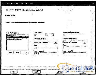
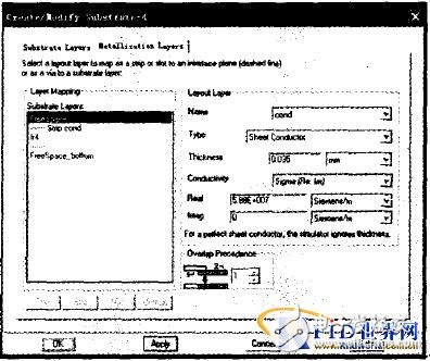
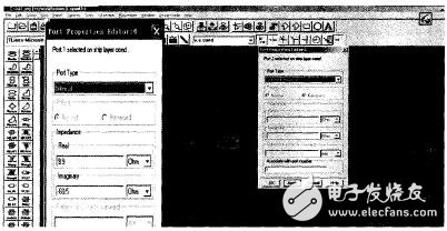
Radio frequency identification technology is an automatic identification technology that uses radio frequency signals to identify objects. The RFID system consists of electronic tags (including chip and tag antennas), readers (including reader antennas), and background hosts. Currently, the radio frequency identification operating frequency includes low frequency (125KHz, 134KHz), high frequency band (13.56MHz), UHF ultra high frequency band (860 ~ 960MHz) and microwave frequency band above 2.45GHz. For an RF~, nOJIJ (RFID) system, the tag antenna is one of the important components that plays a key role in tag-to-reader data communication. The tag antenna acts on the RFID system as much as the eye does for humans. Among the common UHF RFID tag antennas, planar antennas occupy a considerable proportion, for example, microstrip antennas, slot antennas, and the like. In the design of planar antennas, many traditional design techniques are still in use today. However, as the performance requirements of the system continue to expand, the traditional design techniques of antennas have faced many problems and challenges. The RF simulation software ADS fAdvanced DesignSystem1 software, which was launched by Agilent, USA, is a large-scale integrated design software developed on the basis of HP EESOF series EDA software. It is powerful, concise and intuitive, and can be applied to the design of RF and microwave circuits, communication system design, DSP design simulation, and can also be used for the design of planar structure antennas. The design of UHF RFID tag antennas by RF simulation software ADS and the design of common planar structure antennas are different in some respects. In order to achieve maximum power transmission, it is necessary to consider the antenna design and the impedance matching of the tag chip connected thereto. . The following is an example of the procedure for designing a UHF RFID tag antenna using the RF simulation software ADS. Click File One New Project to set the project file name and storage path; click Length Unit to set the length unit to mm. Create a new ADS LAYOUT file. When drawing, consider whether it is a single-sided or double-sided antenna. Here we take the design of a tag antenna using a FR4 single panel as an example. Set the Substrate Layer and MetallizaTIon Layer separately. 3.1 Substrate Layer settings From the main menu, use the following method Momentum=â€substrate=â€create/M0d, Go to the Substrate Layer to define the dialog window. Here we set the required layer structure of the antenna as shown in Figure 1. It can be seen that the ordinary FR4 plate (dielectric constant is about 4.6), the loss tangent Loss Tangent is 0.018, and the plate thickness is 1.5 mm. 3.2 MetallizaTIon Layer (metal layer) settings From the main menu, use the following method Momentum = "Substrate = "Create / Modify" to enter the MetallicizaTIon Layer definition dialog window (Figure 2). Here are the settings: fill the conductivity in ConducTIvity, and fill the metal thickness in Thickness. The conductivity of copper is 5.78E+OO6 and the thickness is 0.035ram. Click Apply and OK after all these settings are complete. The port impedance setting of the tag antenna is different from that of the normal antenna port. It is not a common 50tq or 750, and the tag chip connected to it is impedance matched. In ADS, first select plus two ports. Then use the mouse to select the port, edited by Momentum = "Port Editor". Since GND is removed from the previous layer definition, Single Port (Not Available) cannot be defined, so this design uses an internal port with a Ground Reference Port. In the setting of Port 2, in the Associate with port number, 1 is written, indicating that Port2 is the reference ground of Port1. The impedance parameter of the port is filled in the Real and Imaginar of Port1 (note that the impedance of the tag chip connected to it is matched. Here we use TI's RI-UHF-STRAP-08 chip, the chip at 915 MHz. The impedance is 9.9-j60.53 ohms, as shown in Figure 3. Before Momentum simulation, we set the mesh Mesh in Momentum = "Mesh=" setuD. The setting of Mesh determines the precision of the simulation. Generally, the larger the Mesh Frequency and the Numer er of Cells Per Wavelength, the higher the accuracy. But this comes at the cost of an increase in simulation time. Sometimes it is necessary to trade the reduction in accuracy for a reduction in simulation time. In this example, we use the default value of Mesh, namely: Mesh Frequency is the upper frequency limit of 990MHz in the latter S simulation, and the Numb er of Cells Per Wavelength is 2O. Then select Simulation-s parameters in the main menu Momentum, a dialog box appears to set the S-parameter simulation, as shown in Figure 4. You can select it in Sweep Type, then click update and Simulate to start the simulation, and get the s-parameter simulation result. 3.7V Lithium Polymer Battery,3.7 V Li Polymer Battery,3.7 V Lithium Ion Battery,3.7 V Lithium Polymer Rechargeable Battery Langrui Energy (Shenzhen) Co.,Ltd , https://www.langruibattery.com

