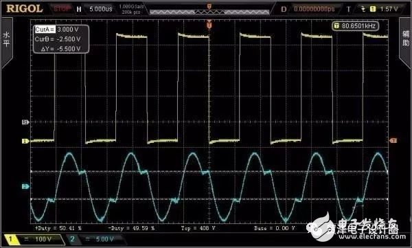
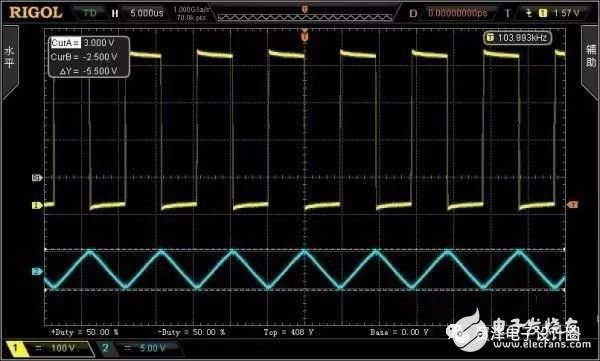
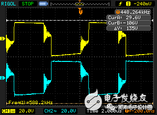
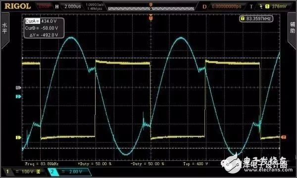
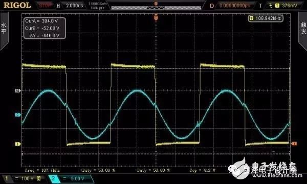
The LLC circuit features low switching losses for high frequency and high power designs. However, many people will encounter the problem that the power of the LLC circuit designed by themselves is low, which leads to various problems of low power of the LLC circuit. This article will take a half-bridge resonant LLC as an example to comprehensively observe the cause of low power and try Give the corresponding solution. In this example, LLC and PFC are basically running, but the efficiency is only 88%. After several tests, the following set of parameters can be obtained, and 87-88% of the efficiency can be obtained, so it cannot continue to improve. Below are the parameters and waveforms of the resonant network. PFC iron silicon aluminum magnetic ring AS130, outer diameter 33mm, magnetic permeability 60, inductance 330uH, 75 ring 0.75MM copper wire. PFC diode: MUR460; PFCMOSFET: 7N60; PFC output voltage 395V, can operate normally; Load: output 24V, 6A146W; LLC level resonant network: Resonant inductance: Ls175uH; Resonant capacitor: Cs, 15nF; Excitation inductance: Lm, 850uH; M=Lm/Ls=5; Q=0.5; Fr=100KHZ; Magnetic core: EER3542/Np44/5/5 transformer åŒ 8.5, primary 3 shares 0.4, secondary 6 shares 0.4. Switch: 7N60 Diode 20/150 Schottky (no special matching power device, 60V after calculating the diode.) Full load 150W switching frequency 82K, slightly lower than the resonant frequency, the waveform shown in Figure 1, it seems normal. figure 1 Yellow is the midpoint of the half bridge Blue is the current wave of the resonant network tested with a current transformer. Here are a few thought points for inefficiencies and try to find out the reasons for inefficiency. Thinking 1 Because it works below the resonant frequency, it is also in the ZVS state, and the secondary can be ZCS. So it is also more attractive. However, the primary MOSFET turn-off current is the maximum current of the magnetizing inductance, so the lower magnetizing inductance will cause the MOSFET to be turned off. In the first parameter, the primary magnetizing inductance is only 550uH. For this point, the parameters of the resonant network are recalculated, and the magnetizing inductance is increased to 850uH, but the problem still exists. The efficiency is still slightly improved compared to the 550uH magnetizing inductance, and the peak value of the magnetizing inductor current seen at least at no load is reduced. figure 2 Thinking 2: The secondary diode stops transmitting after the primary resonant network current equals the current of the magnetizing inductance, naturally blocking the ZCS. However, when the load is full, the oscillation will be severe. Will this phenomenon deteriorate the efficiency, or does it have no effect? Full load 150 watts, secondary diode voltage waveform, no test current waveform. image 3 Thinking 3: Since the overload protection considered uses a diode clamp and two resonant capacitor schemes, it is not known whether this has an effect on efficiency. In response to these considerations, the corresponding amendments are given below. Recommendation 1 Increase the operating frequency of the point, or test the sense of the actual resonant inductance and the capacitance of the resonant capacitor, calculate the resonant frequency, set the switching frequency slightly better than the resonant frequency, because the equivalent switch will be caused by the dead zone. The frequency is reduced. Recommendation 2 Under the condition that the gain is satisfied, the switching frequency should not be too low when the load is heavy, because the leakage inductance of the secondary side and the junction capacitance of the primary side resonate when the load is heavy. Recommendation 3 The efficiency of the whole machine is low, and it is necessary to separately test the PFC and DCDC parts separately, and observe which part causes the efficiency to be low. Simply increasing the magnetizing inductance, although reducing the field current, is not good for achieving ZVS conditions, in order to achieve ZVS requires a longer dead zone to make up. Efficiency does not necessarily increase. Recommendation 4 If the PFC part efficiency is relatively small, it is recommended to use CRM or DCM mode. If space is not a problem, ferrite can be used to improve efficiency. Efficiency is related to many factors and there is no absolute reference value. On the basis of the selection of the semiconductor device, it is sufficient to optimize the efficiency by modifying the parameters of the resonant element. The Q value can be calculated and can be seen on the waveform. After the secondary zero current is turned off, the excitation current is still rising, that is, the resonant capacitor capacity is too large. Or you can first increase the cross-sectional area of ​​the secondary winding, and then observe the efficiency. Further modification After using the above suggestions, test again. The efficiency of this full 30-minute test was 89.6%, which was 1% higher than the previous parameters. Here are the various parameters for this time: Vacin=220V Vpfcin=396V Vo=24V IO=6A CORE: EER3542/PC40 Ls=173uH M=5 Lm=850uH Cs=14nF Fs=103KHz Gnor=1.118 Gmax=1.165 Gpk=Gmax*1.1=1.28 N=9 Qe=0.52 Figure 4 Thinking from the parameters: The increase in inductance reduces the magnitude of the field current and reduces the turn-off loss of the primary MOSFET. The reduction in primary turns was reduced from 44 to 36. The secondary current density increases from 6 and 0.4 to 8 and 0.4. The peak gain does not take into account the minimum input voltage of 360V, but starts from 380V, because the maximum gain required (the voltage divider ratio of the voltage divider network) needs to be small, only 1.16, only consider the 10% margin (actual gain to Peak), the network divider ratio required to meet the output voltage is only 1.28. Select 0.52 according to the Q value table. The component values ​​of the resonant network are then obtained. Due to the large resonant inductance, the physical distance between the primary and secondary needs to be increased to 6-8mm to ensure a leakage inductance of 170uH. A suitable amount of leakage inductance can be obtained by controlling the physical distance between the primary and secondary. The E switching frequency is still below the expected resonant frequency, and the switching frequency should be raised to near the resonant frequency. (Insufficient switching frequency is still too low than the resonant frequency) Reduce the primary 36 laps to 34 laps with a åŒ ratio of 8.5. However, since the leakage inductance of the primary turns is also changed, the leakage inductance Ls=155uH is required to recalculate the value of the resonant network, and the Cs=12nF resonant frequency is close to 115KHZ. The magnetizing inductance is 750uH. When the parameters are fully loaded, it is found that by reducing the turns ratio to reduce the gain value of the resonant network at full load, the switching frequency is effectively and effectively improved. The switching frequency at full load is 109K and the resonant frequency is 115K, which is relatively close. Observing the current waveform also has a good effect. As shown in Figure 5. Figure 5 This article has carried out a more practical and comprehensive analysis of the low efficiency of the LLC circuit, and gives the same comprehensive rectification method. If you are experiencing the same problem in the design process, it is better to read the following article carefully, you may find the corresponding solution. This article is reproduced from the power supply R & D elite circle reprint address: https://mp.weixin.qq.com/s/5neFeKOkTS9nqRDOYevEHA statement: This article is a reprint article, reprint this article is to pass more information, the copyright belongs to the original author, if involved Infringement, please contact Xiaobian for processing. Deployable Drums,Deployable Drum With Wheels,Portable Pre-Terminated Cable Drum,Pre-Terminated Cable Drum ShenZhen JunJin Technology Co.,Ltd , https://www.jjtcl.com