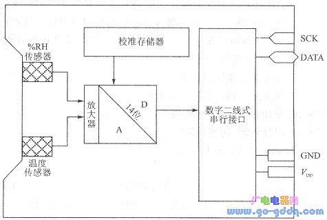
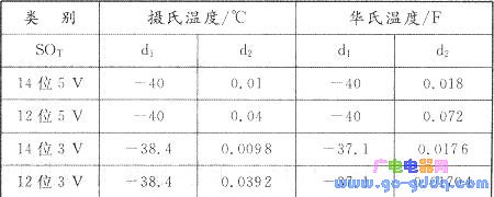
[Applications] Humidity measurement circuit Available in LCC-8 foot surface mount package. The voltage is 2.4V-5.5V. Internal structure and working principle: It mainly includes a relative humidity sensor (a humidity sensitive capacitor made of a special liquid crystal polymer), a band gap temperature sensor (its output voltage is proportional to temperature, abbreviated as VPTAT), an amplifier, a 14-bit A/D converter, and a calibration memory. And two-wire serial interface and other circuits. (1) Humidity The relative humidity reading of the SHTlx/SHT7x output is nonlinearly related to the measured relative humidity (RH). In order to obtain accurate data on relative humidity, the reading values ​​must be nonlinearly compensated. The formula for compensating for nonlinearity is: (2) Temperature The temperature sensor reading value is also non-linear, and must be substituted into the formula (1.2.3) to calculate the measured temperature value T (°C): Where di and dz are constants, the values ​​of d1 and d2 in different cases can be determined according to Table 1.2.1. Table 1.2.1 Selection of d1 and d2 values (3) Dew point Dew point is also an important parameter in humidity measurement, which indicates the temperature at which condensation initially occurs during water vapor cooling. To calculate the dew point, Sensirion also provided the user with a program to measure the dew point "SHTlxdp. bs". The program can be used to control the on/off of the internal heater, and then calculate the dew point based on the measured temperature value and relative humidity value. When you run this program on the command and response interface, the prompt will appear on the computer screen, >". The user first enters the letter "S" from the keyboard, and then enters the corresponding number to get the following results: When the number "1" is input, the temperature is measured and displayed in degrees Celsius dgC= xx.x; When the number "2" is entered, the relative humidity % RH = xx.x is measured and displayed; When inputting the number "3", turn on the heater to increase the temperature of the sensor by 5 °C; When the number "4" is entered, turn off the heater to cool the sensor; When the number "5" is entered, the dew point temperature dpC= xx.x is displayed. (4) Two-wire serial interface The two-wire serial interface includes a serial clock line (SCK) and a serial data line (DATA). The SCK is used to receive the serial clock signal sent by the microcontroller to keep the SHTlx/SHT7x in sync with the host. DATA is a three-state terminal that can input data as well as output measurement data. When not in use, it is in a high-impedance state. Data can only be updated at the time when the falling edge of DATA has elapsed and SCK is at the rising edge. In order to make the data signal high, a 10 kΩ pull-up resistor is required between the data line DATA and the UDD terminal. This pull-up resistor is usually included in the microcontroller's I/O interface circuit. The minimum frequency of the serial clock is not limited and the chip can operate at very low frequencies. It should be noted that the two-wire serial interface is not compatible with the microcontroller bus. [Substitution interchange compatible] [SHT1x original (Chinese) data sheet (Datasheet) package PDF] Intel Nuc I5,Intel Nuc 11 I5,I5 Mini Pc,Intel Nuc 10 I5 Guangdong Elieken Electronic Technology Co.,Ltd. , https://www.elieken.com


![]()
