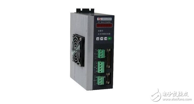
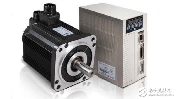
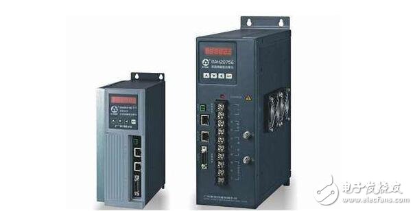
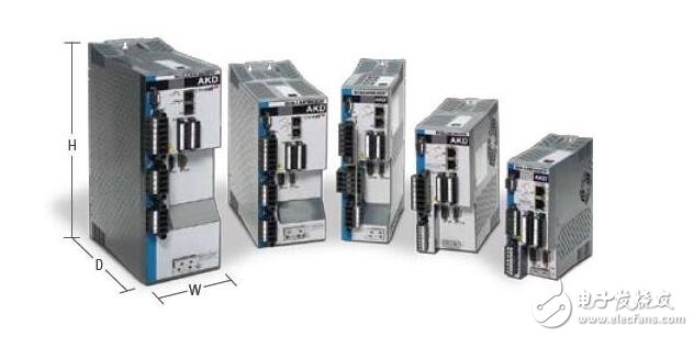
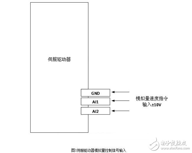
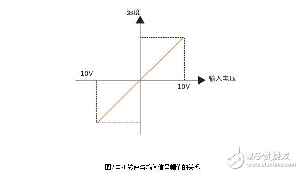
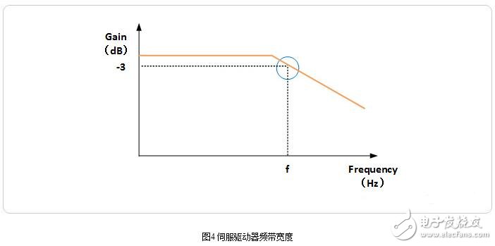
Servo drives are an important part of modern motion control and are widely used in automation equipment such as industrial robots and CNC machining centers. Especially for servo drives for controlling AC permanent magnet synchronous motors, it has become a research hotspot at home and abroad. The current, servo, and position 3 closed-loop control algorithms based on vector control are commonly used in current AC servo drive design. The speed closed-loop design in this algorithm is reasonable or not, which plays a key role in the performance of the entire servo control system, especially the speed control performance. Servo feed system requirements 1, wide speed range 2, high positioning accuracy 3, there is enough transmission rigidity and high speed stability 4, fast response, no overshoot In order to ensure the productivity and processing quality, in addition to the high positioning accuracy, it also requires good fast response characteristics, that is, the response of the tracking command signal is required to be fast, because the CNC system requires addition and subtraction during starting and braking. The acceleration is large enough to shorten the transition process time of the feed system and reduce the contour transition error. 5, low speed and large torque, strong overload capability In general, the servo drive has an overload capacity of 1.5 times or more in a few minutes or even half an hour, and can be overloaded 4 to 6 times in a short time without being damaged. 6, high reliability The feed drive system of CNC machine tools is required to have high reliability, good work stability, strong environmental adaptability such as temperature, humidity, vibration and strong anti-interference ability. Motor requirements 1. The motor can run smoothly from the lowest speed to the highest speed. The torque fluctuation is small, especially at low speeds such as 0.1r/min or lower, there is still a smooth speed without creeping. 2. The motor should have a large overload capacity for a long time to meet the requirements of low speed and large torque. Generally, DC servo motors are required to be overloaded 4 to 6 times in a few minutes without damage. 3. In order to meet the requirements of fast response, the motor should have a small moment of inertia and a large stall torque, with the smallest possible time constant and starting voltage. 4. The motor should be able to withstand frequent starts, braking and reversal. At present, the mainstream servo drivers adopt digital signal processor (DSP) as the control core, which can realize more complicated control algorithms, realize digitalization, networking and intelligence. The power device generally adopts the driving circuit designed with the intelligent power module (IPM) as the core. The IPM integrates the driving circuit internally, and has fault detection and protection circuits such as overvoltage, overcurrent, overheat and undervoltage, and adds soft in the main loop. Start the circuit to reduce the impact of the startup process on the drive. The power driving unit first rectifies the input three-phase electric power or the commercial power through a three-phase full-bridge rectifying circuit to obtain a corresponding direct current power. After rectifying the three-phase electric or commercial power, the three-phase permanent-magnet synchronous AC servo motor is driven by the three-phase sinusoidal PWM voltage inverter. The entire process of the power drive unit can be simply the process of AC-DC-AC. The main topology circuit of the rectifier unit (AC-DC) is a three-phase full-bridge uncontrolled rectifier circuit. With the large-scale application of servo system, servo drive use, servo drive debugging and servo drive repair are all important technical issues of servo drives. More and more industrial control service providers have carried out in-depth technical research on servo drives. Servo drives are an important part of modern motion control and are widely used in automation equipment such as industrial robots and CNC machining centers. Especially for servo drives for controlling AC permanent magnet synchronous motors, it has become a research hotspot at home and abroad. The current, servo, and position 3 closed-loop control algorithms based on vector control are commonly used in current AC servo drive design. The speed closed-loop design in this algorithm is reasonable or not, which plays a key role in the performance of the entire servo control system, especially the speed control performance. In automation equipment, servo motors are often used, especially position control. Most of the brand's servo motors have a position control function that controls the servo motor operation by issuing pulses from the controller. The number of pulses corresponds to the angle of rotation, and the pulse frequency corresponds to the speed (related to the electronic gear setting), When a new system, the parameters can not work, first set the position gain, to ensure that the motor is no noise, try to set it larger, The moment of inertia ratio is also very important, and can be referenced by the number set by self-learning. Then set the speed gain and speed integration time to ensure continuous operation at low speed and positional accuracy. 1. Position proportional gain: Set the proportional gain of the position loop regulator. The larger the setting value, the higher the gain and the greater the stiffness. Under the same frequency command pulse condition, the position lag is smaller. However, too large a value may cause oscillation or overshoot. The parameter values ​​are determined by the specific servo system model and load conditions. 2. Position feed forward gain: Set the feed forward gain of the position loop. The larger the set value, the smaller the position lag is at the command pulse of any frequency, and the feedforward gain of the position loop is large, and the high-speed response characteristic of the control system is improved, but the position of the system is unstable and oscillation is likely to occur. When high response characteristics are not required, this parameter is usually set to 0 to indicate the range: 0~100% 3. Speed ​​proportional gain: Set the proportional gain of the speed regulator. The larger the setting, the higher the gain and the greater the stiffness. The parameter values ​​are determined according to the specific servo drive system model and load value. In general, the larger the load inertia, the larger the set value. Set the larger value as much as possible without oscillating the system. 4. Speed ​​integral time constant: Set the integral time constant of the speed regulator. The smaller the setting value, the faster the integration speed. The parameter values ​​are determined according to the specific servo drive system model and load conditions. In general, the larger the load inertia, the larger the set value. Set the smaller value as much as possible without oscillating the system. 5. Speed ​​feedback filter factor: Set the speed feedback low-pass filter characteristics. The larger the value, the lower the cutoff frequency and the less noise the motor produces. If the load inertia is large, the set value can be appropriately reduced. The value is too large, causing the response to slow down and may cause oscillation. The smaller the value, the higher the cutoff frequency and the faster the speed feedback response. If a higher speed response is required, the set value can be appropriately reduced. 6. Maximum output torque setting: Set the internal torque limit value of the servo drive. The set value is a percentage of the rated torque. At any time, this limit is valid. The positioning is completed. The range is set to the position control mode. This parameter provides the basis for the drive to judge whether the positioning is completed under the position control mode. When the number of remaining pulses in the position deviation counter is less than or equal to the set value of this parameter, the drive considers that the positioning is completed, the in-position switch signal is ON, otherwise it is OFF. . In the position control mode, the output position positioning completion signal is output, and the acceleration/deceleration time constant setting value indicates the acceleration time of the motor from 0 to 2000 r/min or the deceleration time from 2000 to 0 r/min. The acceleration/deceleration characteristic is a linear arrival speed range setting arrival speed. In the non-position control mode, if the servo motor speed exceeds the set value, the speed arrival switch signal is ON, otherwise it is OFF. In the position control mode, this parameter is not used. Independent of the direction of rotation. 7. Manually adjust the gain parameters Adjust the speed proportional gain KVP value. After the servo system is installed, the parameters must be adjusted to make the system rotate stably. First adjust the speed proportional gain KVP value. Before the adjustment, the integral gain KVI and the differential gain KVD must be adjusted to zero, and then the KVP value is gradually increased. At the same time, observe whether the servo motor stops when it stops, and manually adjust the KVP parameter to observe whether the rotation speed is obviously fast or not. SLOW. When the KVP value is increased to the above phenomenon, the KVP value must be adjusted back to small, so that the oscillation is eliminated and the rotation speed is stable. The KVP value at this time is the initially determined parameter value. If necessary, after KVI and KVD adjustment, you can make repeated corrections to achieve the desired value. Adjust the integral gain KVI value. The integral gain KVI value is gradually increased, so that the integral effect is gradually generated. It can be seen from the introduction of the integral control that the KVP value and the integral effect increase to the critical value will cause oscillation and instability. Like the KVP value, the KVI value is adjusted back to small, so that the oscillation is eliminated and the rotation speed is stable. The KVI value at this time is the initially determined parameter value. Adjust the differential gain KVD value. The main purpose of differential gain is to make the speed rotate smoothly and reduce the overshoot. Therefore, increasing the KVD value gradually improves the speed stability. Adjust the position proportional gain KPP value. If the KPP value is adjusted too large, the motor positioning overshoot will be too large when the servo motor is positioned, causing instability. At this time, it is necessary to reduce the KPP value, reduce the overshoot and avoid the unstable region; but it cannot be adjusted too small to reduce the positioning efficiency. Therefore, care should be taken when adjusting. 8. Automatically adjust the gain parameters Modern servo drives are micro-computerized, and most provide automatic gain tuning to handle most load conditions. In the parameter adjustment, you can use the automatic parameter adjustment function first, and then manually adjust if necessary. In fact, the automatic gain adjustment also has an option setting. Generally, the control response is divided into several levels, such as high response, medium response, and low response, and the user can set according to actual needs. The driver inputs the sine wave speed command, the amplitude is 0.01 times of the rated speed command value, the frequency is gradually increased from 1Hz, and the corresponding speed curve of the motor is recorded. As the command sine wave frequency is increased, the waveform of the motor speed is sinusoidal to the command. The phase lag of the wave curve gradually increases, and the amplitude gradually decreases. The frequency at which the phase lag is increased to 90° is taken as the frequency bandwidth of the 90° phase shift; the frequency whose amplitude is reduced to 1/√2 times is taken as the -3 dB bandwidth, which is subject to the first condition. The test method is explained below, and for convenience of description, the standard is simply referred to as "General Technical Conditions." Among the control signal terminals of the servo driver, there are 1 to 2 analog voltage signal command input terminals for external input of the speed or torque command, which is often referred to as "the AD port of the servo driver". The general speed command is a sine wave signal with an amplitude of ±10V. As shown in Figure 1. If the servo driver does not set the threshold (voltage dead zone) for the input command, ideally, +10V corresponds to the rated speed of the motor forward rotation, and -10V corresponds to the rated speed of the motor reverse rotation, the change of the command voltage amplitude, and the motor speed. It changes linearly, as shown in Figure 2. "General technical conditions": "Driver input sine wave speed command, the amplitude of which is 0.01 times the rated speed command value". Assume that the speed command amplitude is ±10V, and the motor's rated speed is 6000RPM, that is, when the input amplitude is 0.1V sine wave voltage signal, the servo motor speed is 60RPM. "General Technical Conditions": "The frequency is gradually increased from 1 Hz, and the corresponding motor speed curve is recorded" The sine wave frequency is gradually increased from 1 Hz, as shown in Figure 3. Under the control of the command, the servo motor performs four cycles of forward acceleration - forward deceleration - reverse acceleration - reverse deceleration for one cycle, and the sine wave command signal at a certain frequency, the servo motor The maximum speed is 60RPM. As the frequency of the command sine wave increases, the waveform of the motor speed gradually increases the phase lag of the command sine wave curve, and the amplitude gradually decreases. "General Technical Conditions": "Measure the frequency at which the phase lag is increased to 90° as the frequency bandwidth of the 90° phase shift; the frequency whose amplitude is reduced to 1/√2 times is taken as the -3dB bandwidth, which is achieved first. The conditions shall prevail." Take the amplitude frequency curve as an example, as shown in Figure 4. At this time, the frequency f is the bandwidth of the servo driver.
ALL Kinds of 4G NB Vehicle GPS Tracker, there must be one which should meet your expectation.
ES810-CM the hot-sell with certificates of FCC,CE, PTCRB, Verizon, AT&T,T-Mobile, Sprint.
ES811 the waterproof version of ES810 with certificates of Verizon, Sprint.
ES840 the OBDII with certificates of FCC, Verizon, Sprint.
ES821 the smallest asset GPS Tracker with the certificates of FCC, CE,T ELEC, Verizon, T-Mobile, Sprint.
ES826 the long standby with the certificates of FCC, PTCRB, TELEC, AT&T, Verizon, Sprint.
ES410 the BG95(NB) version of ES810
ES420 the BG95(NB) version of ES821
ES430 the BG95(NB) version of ES826
NB vehicle GPS Trackers,NB car GPS Trackers,Waterproof car GPS Tracker,IP65 car GPS Tracker,OBDII NB vehicle GPS Trackers,Wireless NB GPS Trackers eSky wireless Inc , https://www.eskygpsiot.com