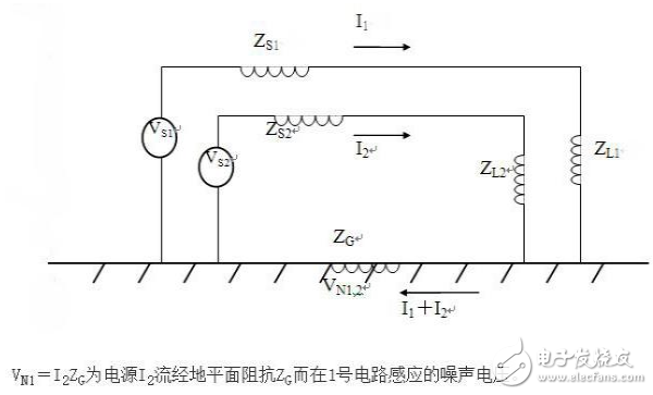
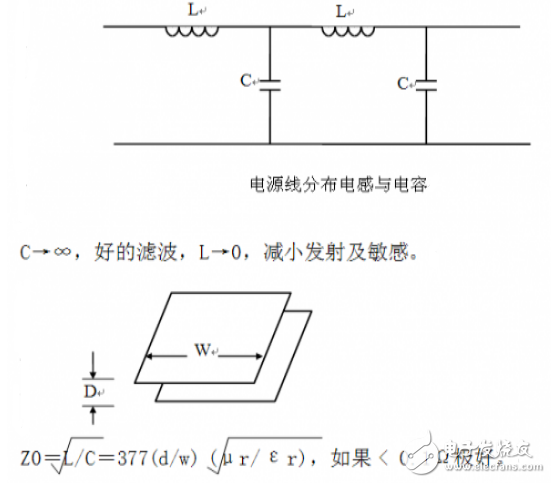
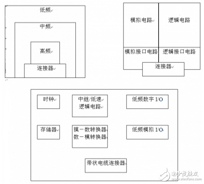
This specification simplifies EMC's main principles and conclusions, and is a reference for hardware engineers in development and design. The three elements of electromagnetic interference are interference sources, interference transmission paths, and interference receivers. EMC is working on these issues. The most basic interference suppression techniques are shielding, filtering, and grounding. They are mainly used to cut off the transmission path of interference. Generalized electromagnetic compatibility control techniques include suppressing the emission of interfering sources and increasing the sensitivity of interfering receivers, but have extended to other disciplines. This specification focuses on the EMC design of the board, with some necessary EMC knowledge and rules. Electromagnetic compatibility considerations during the printed circuit board design phase will reduce electromagnetic interference in the prototype. The types of problems include common impedance coupling, crosstalk, radiation generated by high frequency current carrying wires, and noise picked up by loops formed by interconnect wiring and tracks. In high-speed logic, such problems are particularly fragile for many reasons: 1. The impedance of the power supply and the ground line increases with increasing frequency, and the common impedance coupling occurs more frequently; 2, the signal frequency is higher, coupled to the step line through parasitic capacitance is more effective, crosstalk occurs more easily; 3. The signal loop size is comparable to the clock frequency and the wavelength of its harmonics, and the radiation is more significant. 4. The impedance mismatch problem caused by the signal line reflection. 1, 5-15 rules, that is, the clock frequency to 5MHz or pulse rise time is less than 5ns, the PCB board must use multi-layer board. 2. Different power planes cannot overlap. 3. Common impedance coupling problem. model: Since the ground plane current may be generated by multiple sources, the induced noise may be higher than the sensitivity of the mode or the immunity of the electrical. Solution: 1 analog and digital circuits should have their own circuits, and finally single point grounding; 2 The wider the power cord and the return line, the better; 3 shorten the length of the printed line; 4 power distribution system decoupling. 4. Reduce the loop area and the cross-link area of ​​the two loops. 5. An important idea is that the EMC on the PCB mainly depends on the Z of the DC power line. Here are the board layout guidelines: 1, the crystal is as close as possible to the processor 2, analog circuit and digital circuit occupy different areas 3. The high frequency is placed on the edge of the PCB and arranged layer by layer. 4, fill the empty area with land 1. The power cord and the return line are as close as possible, and the best way is to go one by one. 2. Provide a zero-volt return line for the analog circuit, and the signal line and the return line are small and 5:1. 3. For crosstalk of long parallel traces, increase the spacing or add a zero volt line between the traces. 4, manual clock wiring, away from the I / O circuit, you can consider adding a dedicated signal return line. 5. The critical lines, such as the reset line, are close to the ground return line. 6. To minimize crosstalk, use double-sided #-type wiring. 7, high-speed line to avoid going straight. 8. The strong and weak signal lines are separated. The company adheres to the management policy of "seeking truth and dedication" and a strict quality assurance system. In the new century, we will follow the tenet of "innovation, progress and rigor" and a forge ahead enterprise with "excellent quality and excellence". Spirit, the supreme product, add wings to your enterprise take off. Carefully do a good job of each product, the highest quality, and integrate a dedicated attitude, dedicated spirit, skilled practice, and good reputation into the details of the service. High Voltage Connector,High Voltage Terminal Wire Connectors,High Voltage Terminal Connectors,High Voltage Terminal Connector Terminal Sichuan Xinlian electronic science and technology Company , https://www.sztmlch.com

