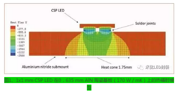
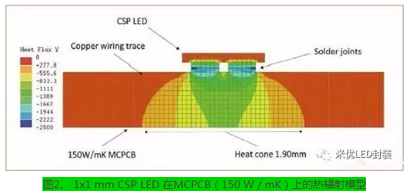
What is CSP? A CSP (chip scale package) package refers to a package technology in which the size of the package itself does not exceed 20% of the size of the chip itself (the next generation technology is a substrate level package, and the package size is the same as the chip). To achieve this, LED manufacturers minimize unnecessary structures, such as using standard high-power LEDs, removing ceramic heat-dissipating substrates and connections, metallizing P and N poles, and directly overlying the LEDs. According to Yole Développement, CSP packaging will account for 34% of the high-power LED market by 2020. Why is the CSP package facing thermal challenges? The CSP package is designed to be soldered directly to a printed circuit board (PCB) through metallized P and N poles. In some respects it is a good thing, this design reduces the thermal resistance between the LED substrate and the PCB. However, since the CSP package removes the ceramic substrate as a heat sink member, this allows heat to be transferred directly from the LED substrate to the PCB board and becomes a strong point heat source. At this time, the heat dissipation challenge for CSP has changed from “level 1 (LED base level)†to “second level (whole module level)â€. In response to this situation, the designer of the module began to use a metal-covered printed circuit board (MCPCB) to cope with the CSP package. Figure 1. Thermal radiation model of a 1x1 mm CSP LED on a 0.635 mm AlN ceramic substrate (170 W/mK) As can be seen from Figures 1 and 2, the researchers conducted a series of thermal radiation simulation tests on MCPCB and aluminum nitride (AlN) ceramics. Due to the structure of the CSP package, the heat flux is only transmitted through the solder joints with a small area. Most of the heat is concentrated in the center, which leads to reduced service life, reduced light quality, and even LED failure. The ideal cooling model for MCPCB Often the structure of most MCPCBs: the surface of the metal is coated with a surface copper of approximately 30 microns. At the same time, the metal surface is covered by a layer of resin medium containing thermally conductive ceramic particles. However, excessive thermal ceramic particles can affect the performance and reliability of the entire MCPCB. At the same time, there is always a trade-off between performance and reliability for the heat transfer medium layer. According to the analyst's analysis, in order to better heat dissipation, MCPCB needs to reduce the thickness of the dielectric layer. Since the thermal resistance (R) is equal to the thickness (L) divided by the thermal conductivity (k) (R = L / (kA)), and the thermal conductivity is determined only by the properties of the medium itself, the thickness is the only variable. However, because the dielectric layer cannot be reduced indefinitely due to production process limitations and service life, researchers need a new material to solve this problem. How do nano ceramics become the best solution for MCPCB? The researchers found that an electrochemical oxidation process (ECO) can produce a layer of tens of microns of alumina ceramic (Al2O3) on the aluminum surface, while the alumina ceramic has good strength and relatively low thermal conductivity (about 7.3 W/mK). However, since the oxide film is automatically bonded to the aluminum atom during the electrochemical oxidation process, the thermal resistance between the two materials is lowered, and the structural strength is also possessed. At the same time, the researchers combined nanoceramics with copper to give the overall thickness of the composite structure a very high total thermal conductivity (about 115 W/mK) at very low temperatures. Therefore, this material is well suited to the needs of CSP packages. in conclusion As designers continue to explore materials for the right CSP package, they often find that their needs have surpassed existing technology. The heat dissipation problem has led to the birth of nano-ceramic technology, which can fill the gap between traditional MCPCB and AlN ceramics. This will enable designers to introduce more compact, clean and efficient light sources.
Knowing which specific Mac model you have is important.
Please contact with me, that I can tell you about your Mac model and generation will be displayed.
macbook 85w charger,apple macbook 85w charger,85w charger for macbook pro Shenzhen Waweis Technology Co., Ltd. , https://www.laptopsasdapter.com


How to solve the heat dissipation problem of CSP package?
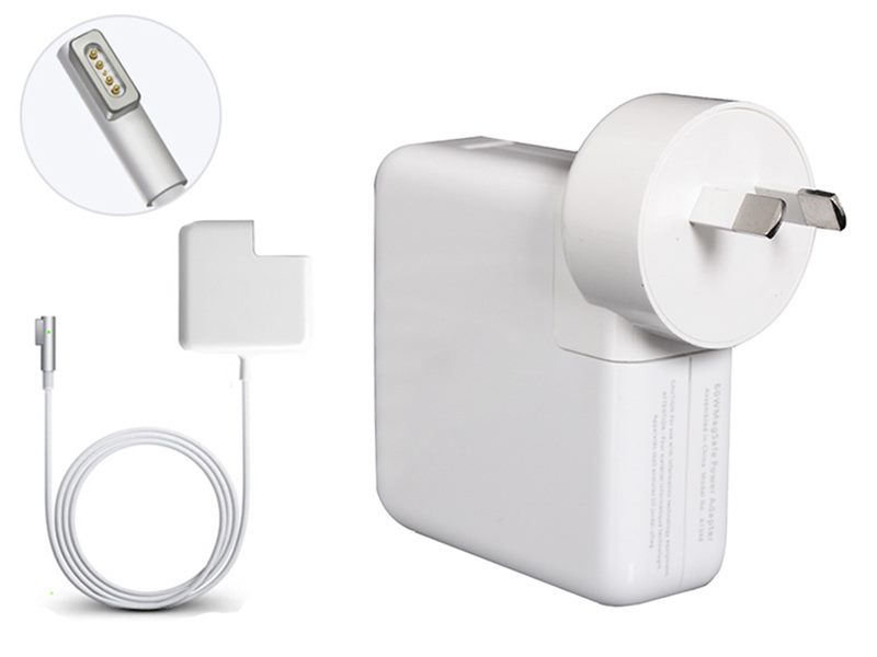
The 85W Macbook Charger MagSafe 1 or MagSafe 2 Power Adapter features a magnetic DC connector so if someone should trip over it, the cord disconnects harmlessly and your MacBook Pro stays put safely. It also helps prevent fraying or weakening of the cables over time. In addition, the magnetic DC helps guide the plug into the system for a quick and secure connection.
When the connection is secure, an LED located at the head of the DC connector lights up; an amber light lets you know that your notebook is charging, while a green light tells you that you have a full charge. An AC cord is provided with the adapter for maximum cord length, while the AC wall adapter (also provided) gives you an even easier and more compact way to travel.
Designed to be the perfect traveling companion, the adapter has a clever design which allows the DC cable to be wound neatly around itself for easy cable storage.
This power adapter recharges the lithium polymer battery while the system is off, on, or in sleep mode. It also powers the system if you choose to operate without a battery.
Compatible with MacBook Pro with Retina display.
Not sure if this is the right power adapter for your Mac?
See this article for more details about choosing the right one.