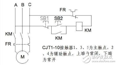
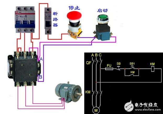
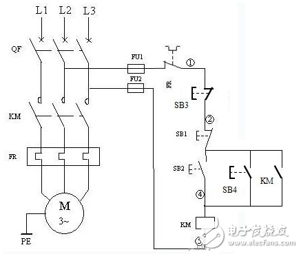
Start stop circuit diagram _ Start stop button wiring diagram: FR---thermal relay, SB 1--Jog stop switch, SB2--Jog start start, close KM--contactor coil KM--contactor normally open contact Working principle circuit diagram Circuit diagram for the motor 2 control circuit. In the figure, SB1 and SB2 are set to A to start and stop control buttons; SB3 and SB4 are to B to start and stop control buttons, and 2 sets of buttons collectively control the motor M. Many control circuit characteristics are: stop button in series, start button in parallel. How the circuit works Start: press A and B (optional) start button SB2 or SB4 → KM coil to get electricity → its normally open auxiliary contact closes and lock → its main contact is closed. Connect the motor main circuit → motor M to run. Stop: press A and B (optional) stop button SB1 or SB3 → KM coil is de-energized → its normally open auxiliary self-locking contact disconnects the self-locking circuit → its main contact is released to disconnect the motor main circuit → the motor M stops Operation. Pump start and stop control circuit as shown.
What is a Capsule Slip Ring?
Capsule slip rings are a type of electrical connector that are used to transfer power and data between two rotating objects. They are commonly used in applications where there is a need to send or receive signals from a stationary object to a rotating one, or vice versa.
How Does it Work?
Capsule slip rings work by using a series of electrical contacts that rotate with the object on which they are mounted. These contacts are spaced evenly around the circumference of the ring, and as they rotate they make and break contact with corresponding contacts on the other object. This allows power and data to be transferred between the two objects without any interruption.
Advantages of Capsule Slip Rings
There are several advantages to using capsule slip rings in place of other types of electrical connectors.
For example, the rotation of the contacts causes them to be freely accessible and therefore free from dust and debris. This makes them ideal for applications where connector maintenance is often a problem.
Because the contacts are freely accessible, they can be readily replaced if a fault occurs. They also have very low electrical resistance, making them ideal for transmitting radio frequency signals. Because of the low resistance, this type of connector is often used in high-speed data transmissions.
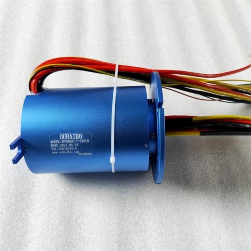
This type of Conductive Slip Ring is similar to the shape of a hat. The brim part is a flange with a conductive slip ring. The function of the flange is to facilitate installation. It is connected to electrical equipment through the fixing hole of the flange. It can be firmly installed on the equipment. Therefore, the stator of the cap-type slip ring is generally fixed by the outer layer with a flange, and the inner part is the rotor with the inner shaft rotating. The stator and the rotor are not fixed, and the details will be different according to the installation method.
Capsule Slip Ring,Split Ring Motor,Slip Ring Motor Connection,Slip Rings In Synchronous Motor Dongguan Oubaibo Technology Co., Ltd. , https://www.sliprobs.com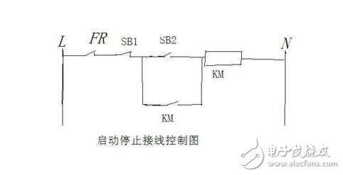
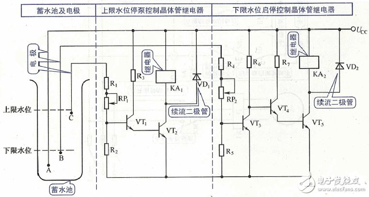
Generator automatic start and stop circuit diagram Daquan (contactor / pump start / stop / motor)
Generator automatic start and stop circuit diagram (1)