Low Frequecny Silicon Steel Transformer,Industrial Control Transformer,Electrical Power Transformer,Line Frequency Transformer IHUA INDUSTRIES CO.,LTD. , https://www.ihua-inductor.com
The MAX9850 is an audio DAC with a unique clock circuit that allows the device to achieve good audio performance over a wide range of main clock frequencies. A typical audio DAC requires the main clock frequency to be an integer multiple of the sampling rate. For example, if the sampling rate is 48kHz, the most commonly used master clock is 48kHz x 256 = 12.288MHz. The MAX9850 can work on a standard audio clock or a common system clock, such as 12MHz, but its performance is reduced. The MAX9850 has a wide range of master clock frequencies, allowing designers to make an appropriate balance between performance and simplified design, and flexibly choose the master clock frequency. Integer mode 1 For best performance, you can use the master or slave integer mode. Both modes require a master clock whose frequency is exactly an integer multiple of the sampling rate. The master mode sets the MAX9850 output word and bit clock; the slave mode sets the MAX9850 input word and bit clock. Figure 1 shows the FFT of the MAX9850 operating in host integer mode. The input signal is a 1kHz, full swing sinusoidal signal with a sampling rate of 48kHz. The main clock is a synchronized 12.288MHz signal. 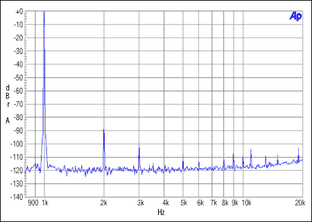
Figure 1. Host integer mode, MCLK = 12.288MHz, FS = 48kHz, 0dBFS
At all frequencies, the distortion amplitude of the host integer mode is equal to or less than -90dB, and the resulting THD + N is -85dB. All distortions appear as harmonics, and signals of this level are difficult for most people to hear. Since the MAX9850 is used for audio recovery in playback systems, these audios have been encoded by lossy algorithms, such as MP3, so the distortion produced by this mode will not restrict the sound quality of the playback link.
In Figure 2, the MAX9850 works in slave mode, using the same clock, sampling rate, and input signal as Figure 1. Since all clocks are synchronized and there is an integer multiple relationship between the clocks, performance is not affected. 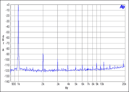
Figure 2. Slave integer mode. MCLK = 12.288MHz, FS = 48kHz, 0dBFS Non-integer mode Although integer mode provides the best performance, it requires a clock frequency that is exactly an integer multiple of the sampling rate (such as sampling rate FS, clock frequency 16 x FS) , Must be accurate. Other circuits in the system generally do not use clock frequencies with integer multiples. In many portable audio systems, the commonly used clock frequency is 12MHz because USB uses this frequency. Since the system already provides this clock, the use of an audio clock will simplify system design relative to a dedicated clock. Although 12MHz is not an integral multiple relationship for all audio sampling rates: 16 x FS, it is an integer multiple of 48kHz. Therefore, using a non-integer multiple clock can easily generate the corresponding internal clock. Figure 3 shows the frequency spectrum when the system uses a 12MHz clock to generate a 1kHz signal, and the signal sampling rate is 48kHz. Compared with the integer mode, the performance of the MAX9850 has decreased in this mode, but it is not obvious. The maximum harmonic is still about 90dB below the signal amplitude, but other non-harmonic distortion components appear in the signal, and THD + N drops to -83dB. 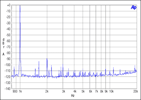
Figure 3. Host non-integer mode, MCLK = 12MHz, FS = 48kHz, 0dBFS
Switching to slave mode (Figure 4) eliminates non-harmonic distortion components and provides almost equivalent performance to integer mode. 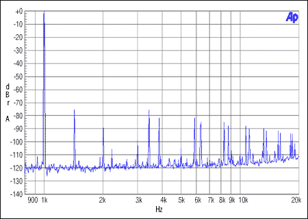
Figure 4. Slave non-integer mode, MCLK = 12MHz, FS = 48kHz, 0dBFS
Figure 5 shows the output FFT of the MAX9850 when the host works in a non-integer mode and works at a 12MHz clock and the input data is sampled at 44.1kHz. Although the sampling rate and the master clock are not integer multiples, the MAX9850 can still reproduce a 1kHz sine wave, and the performance difference is mainly reflected in the higher distortion. Since the working data and clock of the DAC come from a non-integer clock, the distortion generated is not all harmonic distortion. In this mode, the measured THD + N is about -71dB. 
Figure 5. Host non-integer mode, MCLK = 12MHz, FS = 44.1kHz, 0dBFS
In the integer mode, the conversion between the master and slave modes has no effect on performance, but the situation is different in the non-integer mode. The conversion of the master working mode to the slave working mode will further reduce the performance of the converter, as shown in Figure 6. THD + N increased to -65dB. 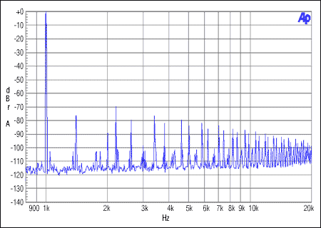
Figure 6. Slave non-integer mode, MCLK = 12MHz, FS = 44.1kHz, 0dBFS
Although the function of distortion and input amplitude is larger signal amplitude, the signal can mask some distortion. However, as the signal amplitude decreases, distortion must be reduced to maintain good sound quality. Figures 7 to 11 show the output spectrum of the MAX9850 at -30dBFS and -60dBFS signal levels. For modes where there is an integer relationship between the master clock and the sampling rate, all distortion components are below the noise floor of the -30dBFS signal amplitude. For the non-integer relationship between the sampling rate and the master clock, such as 44.1kHz and 12MHz, only lower amplitude distortion remains. For the -60dBFS input, the inherent distortion present in this structure begins to appear in the spectrum. This distortion is not directly related to the sampling rate or the master clock, and the result is the same in all modes. 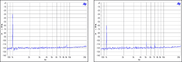
Figure 7. Master / slave, integer mode, MCLK = 12.288MHz, FS = 48kHz, -30dBFS, -60dBFS 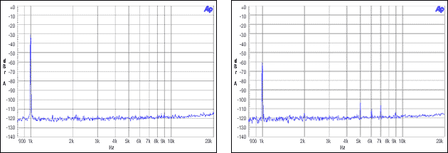
Figure 8. Host non-integer mode, MCLK = 12MHz, FS = 48kHz, -30dBFS, -60dBFS 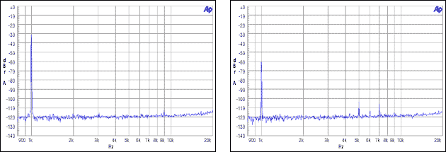
Figure 9. Slave non-integer mode, MCLK = 12MHz, FS = 48kHz, -30dBFS, -60dBFS 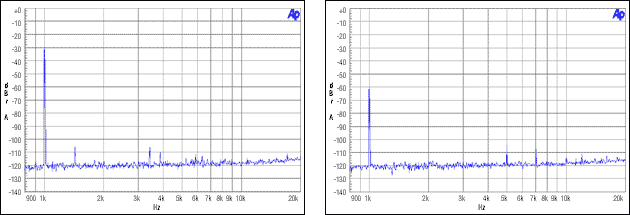
Figure 10. Host non-integer mode, MCLK = 12MHz, FS = 44.1kHz, -30dBFS, -60dBFS 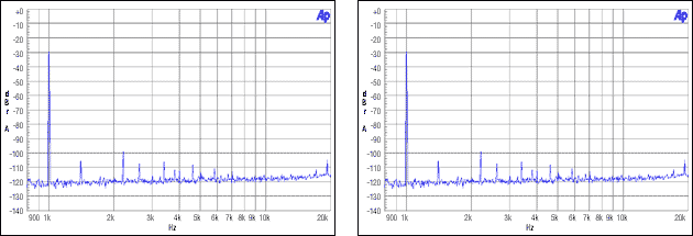
Figure 11. Slave non-integer mode, MCLK = 12MHz, FS = 44.1kHz, -30dBFS, -60dBFS Conclusion Under rail-to-rail input signals, significant distortion can be measured in certain modes. But it will not significantly affect the audio-visual effect. This is because the human ear is sensitive to strong sounds, ignoring the distortion component with a smaller amplitude. Many lossy compression algorithms (for example, MP3 and AAC) use this concept to facilitate compression by removing the signal part masked by the strong tone signal. In both cases, large amounts of data can be eliminated without significantly sacrificing sound quality. Similarly, the converter can also produce some distortion without affecting the sound quality.
When the human ear listens to low-level signals, it can better distinguish the distortion in the signal, because there is no strong signal to provide shielding. For lower level signals, the distortion produced by the MAX9850 is close to or lower than the noise floor, and still maintains good sound quality.
Regardless of the operating mode, the MAX9850 can achieve better signal-to-noise ratio and dynamic range. Since the frequency spectrum generated by the -60dBFS input signal is the same, regardless of the operating mode, the dynamic range is the same in all modes. Similarly, the noise floor of all operating modes is the same, so the signal-to-noise ratio of all modes is the same.
Even in the worst-performing mode, the MAX9850 can achieve effective results. For systems where sound quality is not important, the device can be connected to any system clock to maintain good operation. For systems with high audio quality requirements, it is recommended to provide a specific audio clock to make the DAC work in a fully synchronous mode. Appendix: Measurement Settings Circuit board MAX9850EVKIT Signal generator Audio Precision SYS-2722, PSIA-2722 bit depth: 16 bits Signal analyzer Audio Precision SYS-2722 with PSIA-2722
22Hz to 22kHz bandwidth
A-weighted filtering
FFT input A / D: HiRes A / D @ 65536
FFT samples: 32768
FFT window: Blackman-Harris
Average: 4 power supply Agilent E3630A triple output DC power supply AVDD = 3.0V, PVDD = 3.0V Clock source 12.288MHz generated by PSIA-2722
12MHz generated by the evaluation board crystal oscillator
Audio DAC performance research
Abstract: The MAX9850 audio DAC can work in a wide range of main clock frequencies, and has different performance. By choosing different master clock frequencies, designers can balance performance with simplified design. This application note analyzes the performance of the MAX9850 corresponding to the ratio of different master clock frequencies to sample rates, and shows how the master clock frequency affects device performance.