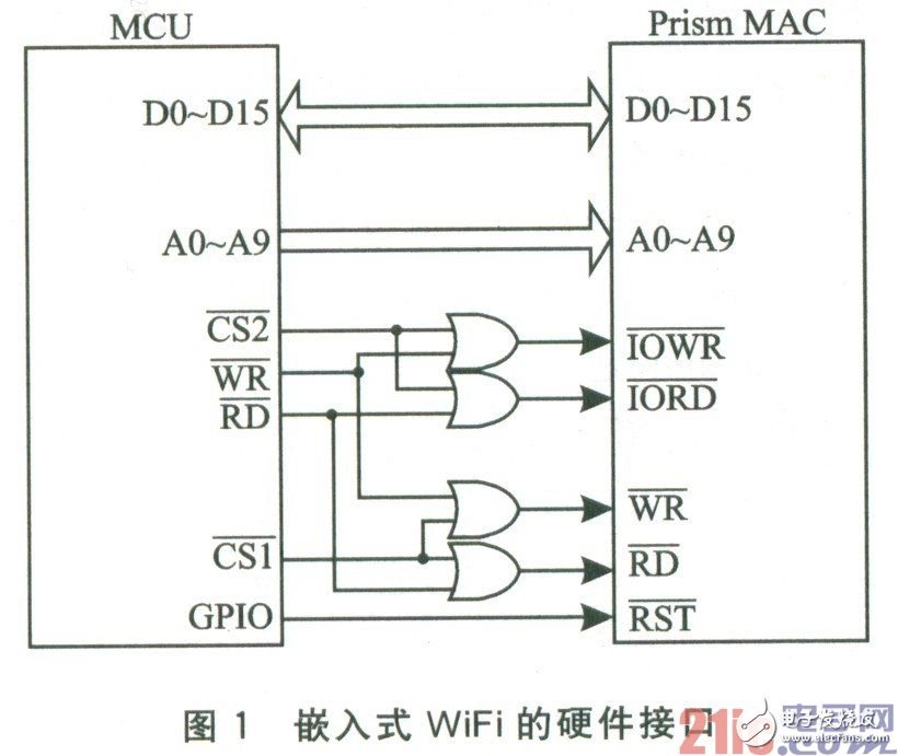
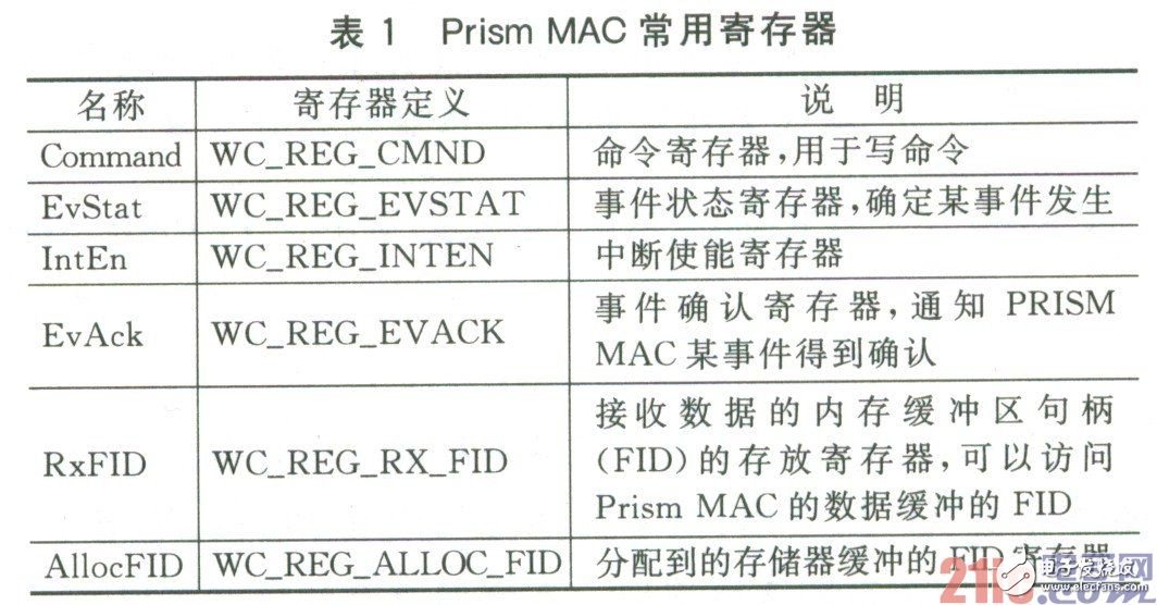
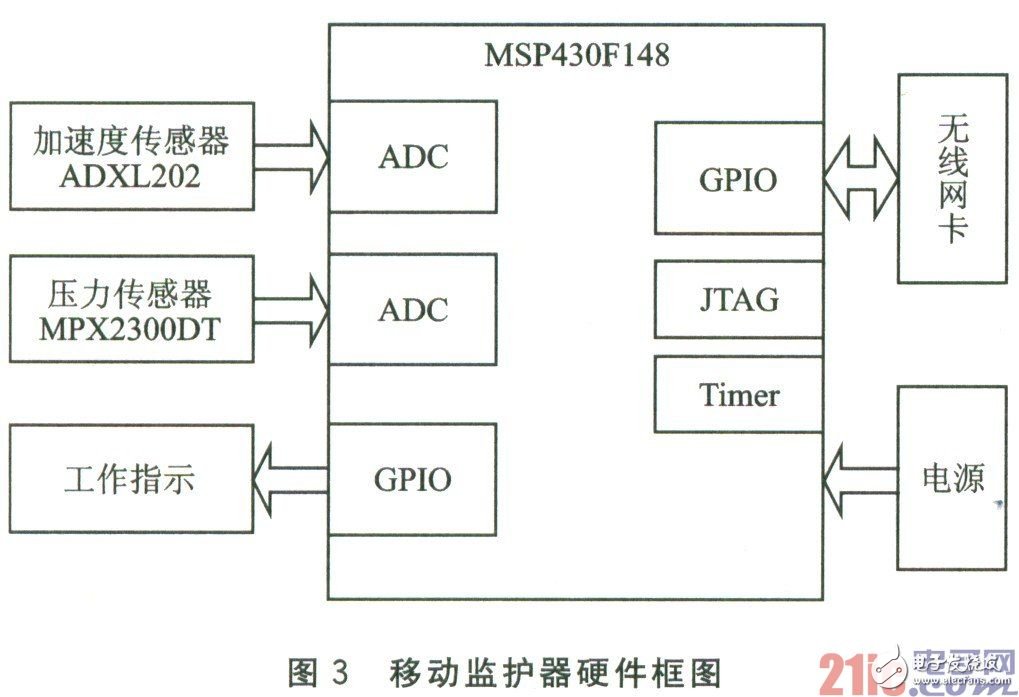
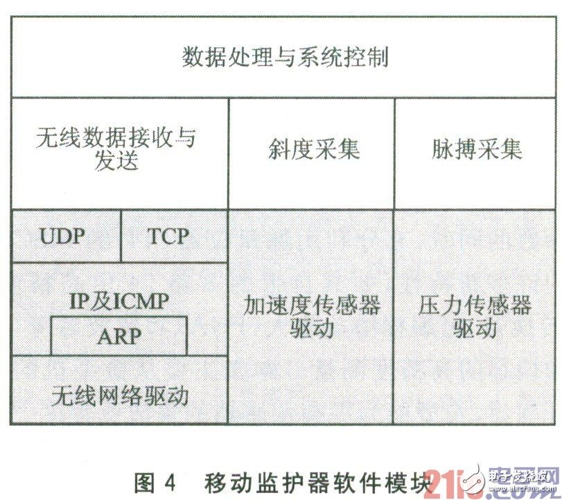
Embedded WiFi technology is a hot spot in current wireless network applications. This article introduces the basic technology of IEEE802.11b, presents a WiFi communication design scheme in an embedded environment; through the concrete realization of a mobile monitoring system, the effectiveness of the scheme is explained. Keywords IEEE802.11b embedded WiFi TCP/IP mobile monitoring At present, the IEEE802.11 wireless local area network standard is widely used in voice communication, wireless office and other fields, but it is mainly limited to wireless communication on general platforms such as PCs and laptops. The application requirements of wireless local area network in embedded environments such as information appliances, industrial control, and mobile handheld devices are increasing. How to integrate WLAN broadband communication in embedded systems has become a hot spot in embedded system applications. 1 IEEE802.11b wireless LAN IEEE802.11 series includes four standards: IEEE802.11, IEEE802.11a, IEEE802.1lb, and IEEE802.1lg. At this stage, there are more products of IEEE802.11b. This article focuses on the IEEE802.1lb standard and introduces the implementation of embedded WiFi. The IEEE802.11b standard is developed on the basis of IEEE802.11. It works in the 2.4 GHz frequency band and adopts CCK modulation technology. The maximum transmission rate can reach 11 Mbps. It has easy deployment, reliable communication, strong anti-interference ability, low cost, Features such as good flexibility, strong mobility, and high throughput. It enables wireless users to obtain Ethernet-level network performance, speed and availability, and can seamlessly integrate multiple LAN technologies to form a network that can meet user needs to the greatest extent. WiFi is the abbreviation of Wireless Fidelity, which specifically refers to the IEEE802.11b wireless standard. Before introducing the working mode of IEEE802.11b, first introduce a few basic concepts. 1.1 The basic concept of IEEE802.11b STA refers to the part that accesses the wireless medium, and is often called a network adapter or a network interface card. The STA can be mobile or fixed. Each STA supports authentication (authenticaTIon), deauthentication (deauthenTIcaTIon), encryption and data transmission. The Basic Service Set (BSS) is the basic building block of the IEEES02.11b LAN. The basic service set can contain multiple STAs. The BSS basic service set has a coverage area. In the coverage area, the member STAs of the basic service set can keep communicating with each other, and each BSS has a basic service set identification code BSSID. Independent BSS (Independent BSS) is the most basic type of IEEE802.11b LAN, and a smallest IEEE802.11b LAN can only contain two STAs. In this mode, STAs can communicate directly. Because this type of IEEES02.11b local area network is usually arranged when needed, this kind of network working mode is usually called ad hoc (Latin, can be translated as "ad hoc network") mode. The relationship between the station (STA) and the basic service set (BSS) is dynamic, and the STA can freely turn on, turn off, enter or leave the BSS coverage area. DSS (DistribuTIon System Service), used to connect multiple BSSs. Due to the limitation of the coverage of the physical layer, the direct communication distance between the STA and the STA that can be supported is determined. In order to solve this problem, DS (Distribution System) is introduced, which can form an extended network with multiple BSSs. AP is the abbreviation of Access Point, which is generally translated as "wireless access node" or "bridge". It mainly acts as a bridge between wireless workstations and wired local area networks in the media access control layer MAC. ESS (Extended Service Set), DS and multiple BSSs allow IEEE802.11 to form a wireless network of any size and complexity. IEEE802.11b calls this kind of network an extended service set network. Similarly, ESS also has an identifying name, namely ESSID. 1.2 IEEE802.11b working mode IEEE 802.1lb has two working modes: Ad-hoe and Infrastructure-structure mode. The IEEE standard defines the set of clients working in the Ad-hoc mode with an independent basic service set (IBSS), and the set of clients working in the Infrastructure mode with the basic service set (BSS). In Ad-hoc mode, the client cannot directly communicate with other clients outside the network. The design purpose of the Ad-hoc mode is to enable clients within the same spectrum coverage to communicate with each other. If a client in an Ad-hoc network model wants to communicate with clients outside the network, there must be a client in the network acting as a gateway and performing routing functions. In Infrastructure mode, each client sends its communication messages to AP. AP forwards all communication messages. These messages can be sent to the Ethernet or to the wireless network. This is an application mode that integrates Ethernet and wireless network architectures. The wireless access node is responsible for command work such as frequency band management and roaming. An AP can connect up to 1024 stations. 2 Design of embedded WiFi The structure of embedded WiFi is different from the implementation on the standard PC/OS platform. To realize WiFi communication on an ordinary microprocessor/microcontroller, its hardware structure and software level must be reduced. The following takes Prism MAC as an example to illustrate the software and hardware design of embedded WiFi. 2.1 Hardware design of embedded WiFi The hardware interface of WiFi in the embedded environment is shown in Figure 1. Compared with the standard platform, there is no PCMCIA bridge in the middle. Figure 1 shows the connection between the PC2MCIA interface network card and the bus open MCU in the embedded environment. Because Prism MAC includes two spaces: Memory space and I/O memory, two chip selects are required to control the choice of read and write space through OR gates. Prism MAC encapsulated by PCMCIA has 26 address lines. To drive Prism MAC, only address lines A0~A9 are needed. All other address lines are grounded. For processors whose bus is not open, you can use I/O port line simulation to read and write. 2.2 Embedded WiFi software design In WinCE, Linux and other operating system environments, you can use the device driver provided by the manufacturer to use the WiFi network card. This kind of system generally has higher requirements for hardware resources (such as CPU performance, memory capacity, etc.). For many embedded applications, due to the limitation of hardware resources, many systems are running in a simple OS (such as uC/0S, etc.) or in an OS-free environment. At this time, the entire software protocol needs to be appropriately reduced. Figure 2 is the software structure of embedded WiFi. In Figure 2, the realization of the TCP/IP protocol has been described in many articles. Here mainly takes Prism MAC as an example to introduce the wireless network driver, that is, the driver of embedded WiFi. Prism MAC provides users with a set of interface registers, and communicates with Prism MAC through these registers. These registers are located in the Attribute Memory [2] space and can be accessed directly using the AttribLlte Memory address. Table 1 lists the commonly used registers of PRISM MAC and their definitions. In order to read and write these registers, two functions are defined: unsigned int getReg (unsigned int reg) and void selReg (unsigned int reg, usnigned int val). The Prism MAC driver sends commands to the command register to operate the MAC. Commonly used commands include allocating buffer, querying network card status, initializing network card, reading data, writing data, etc. The Prism MAC driver needs to provide MAC read and write functions and some control functions for the upper layer. The implemented function prototype is as follows: void init_mac(void) void reset_mac(void) WORD wc_write(WORD*buff, WORD len) WORDwc_read(WORD*buff, WORDmaxlen) B00L get_wlan(void) reset_mac(void) is used to reset Prism MAC when the system is started or the system needs to be reset, and at the same time initialize the variables used by the driver. The inh_mac(void) function completes the initialization of the network controller and firmware, and at the same time applies for the buffer used by the network card controller, and saves the RID that needs to be used. The wc_write (W0RD*burf, W0RD len) function writes the len bytes in the buff into the sending buffer of the MAC, and then writes the sending command to the command register of the network card to send the data. The function returns the actual length of the data sent. The wc_read (WORD*buff, WoRD maxlen) function receives input data. Return the actual received data length. For the upper layer protocol, after calling wc_read, you can do protocol analysis on the data in the buff. For TCP/IP, what actually gets out may be IP, ARP and other types of packets. get_wlan(void) judges whether data is received by accessing the EvStat register, and returns the judgment result. If so, put the PrismMAC data frame into the shared data area. This function just reads the header of the data frame of PrismMAC, which is equivalent to the header of an Ethernet frame. The read data format is After the upper layer protocol calls get_wlan, if the return value is TRUE, variables such as destination address, source address, frame type, etc. can be accessed to determine whether to process the received data. If the data needs to be received, you can call wc_read to read the data. 3 Application of embedded WiFi in medical monitoring Embedded WiFi has a wide range of applications in many fields. Here is a specific implementation of embedded WiFi-a mobile monitoring system. The monitoring system is used for patient monitoring in hospitals, using embedded WiFi technology, which can perform digital grouping and real-time monitoring of the tested objects in a mobile environment. 3.1 Hardware structure The mobile monitoring system consists of a server and multiple mobile monitors. The server side includes a PC or laptop, a wireless AP, and an alarm. The hardware structure and connection method are relatively simple, so I won't explain it here. The hardware structure diagram of the mobile monitor is shown in Figure 3. In Figure 3, the hardware structure of the mobile monitor includes a power supply module, a pressure sensor module, an acceleration sensor module, and a wireless network card module. The mobile monitor uses Ti's ultra-low power consumption microcontroller MSP430F148 as the CPU. The acceleration sensor module uses AD's acceleration sensor ADXL202, which is used for motion acceleration test, or measurement of gravitational acceleration, analysis of tilt, that is, for patient fall test. The pressure sensor uses Motorola Medical’s special MPX2300DT, which has good low-voltage operating characteristics and linear output for pulse measurement. The power supply is powered by a 3.6 V battery, which can meet the power requirements of the mobile monitor after a simple voltage conversion. The wireless network card uses a PCMCIA network card based on the IntersilPrism2 chipset. It is an IEEE802.11b compatible network adapter. 3.2 Software structure In ad-hoc mode, the distance between the mobile monitor and the server is very short. In order to increase the monitoring range, the mobile monitoring system works in Infrastructure mode. The AP and mobile monitor on the server side are equivalent to one STA, and the mobile monitor and server can be in different BSSs. The mobile monitor and the BSS where the AP is located together form an ESS, which uses DSS for communication. The server-side software module is mainly used to separate the slope, mobile monitor configuration information, and pulse information from the data received from the network, and alarm according to the information to control the mobile monitor. The software module of the mobile monitor is shown in Figure 4. The mobile monitor mainly completes acceleration (slope) data collection, pulse signal collection, data transmission and reception, and sensor start and stop control. The software can be divided into two levels: application layer and driver layer. The shaded part is the hardware driver layer, and above the driver layer is the application layer. Since the mobile monitoring system adopts embedded WiFi technology and supports digital grouping, the tested pair can be matched as needed. Detachable Laptop Stand,Foldable Detachable Computer Stand,Detachable Ergonomic Laptop Stand,Detachable And Foldable Aluminum Laptop Stand Shenzhen ChengRong Technology Co.,Ltd. , https://www.laptopstandsupplier.com


