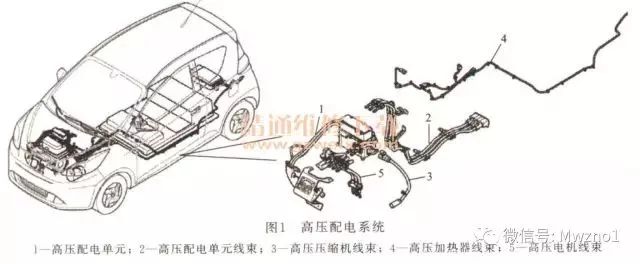
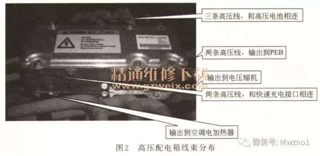
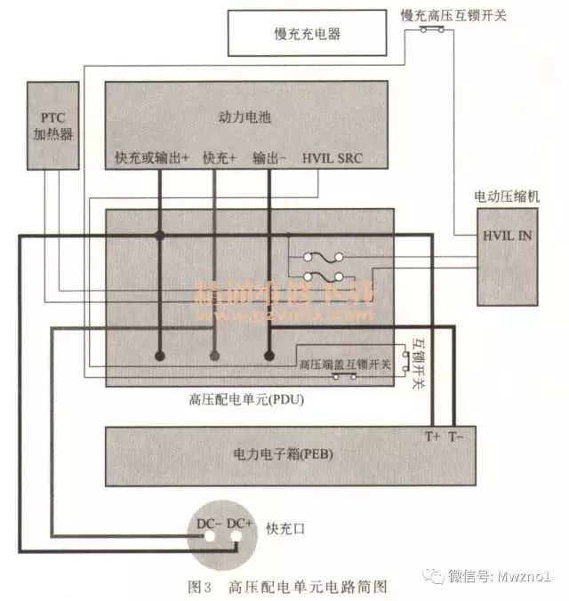
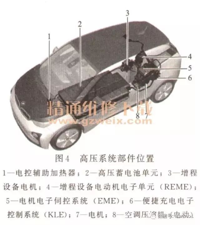
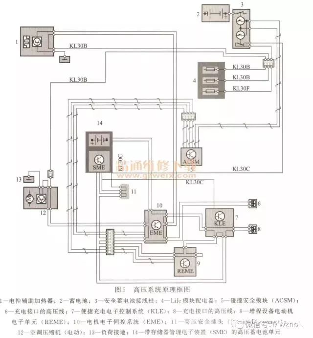
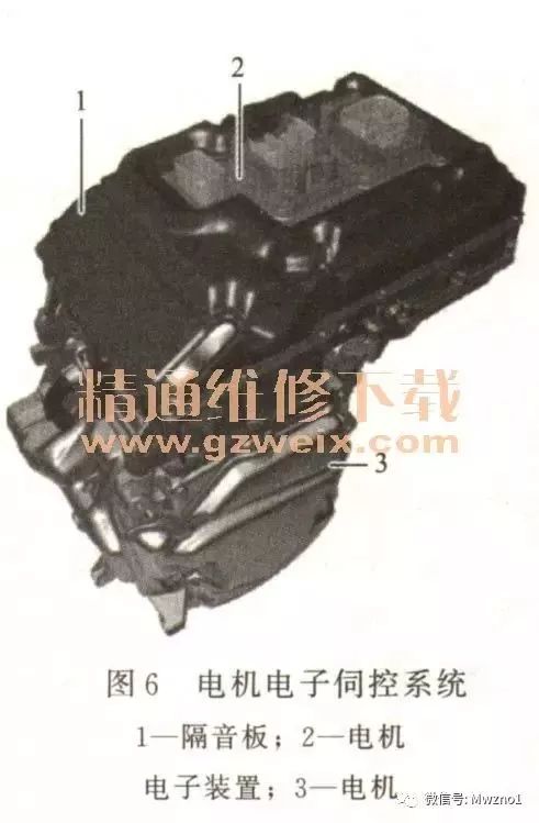
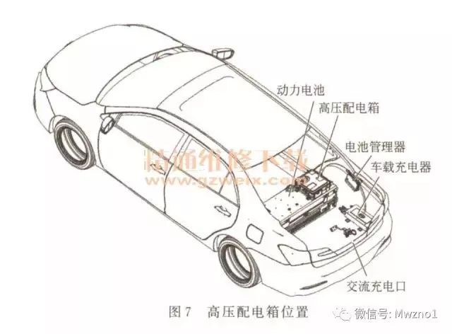
At present, Chengjie Intelligent has more than 150 sets of fully automatic winding equipment and more than 80 sets of automatic production equipment. The company has passed ISO9001 quality management system certification and established a unique corporate culture. It is one of the most cohesive companies in the industry. First, Roewe E50 high voltage power distribution unit The high-voltage power distribution unit (PDU) is located in the front compartment and is fixed on the PEB and PDU tray. The main function is to distribute the high-voltage power of the high-voltage battery pack to each high-voltage electrical appliance, and to the electric air-conditioning compressor and heater. The high voltage circuit acts as an overcurrent protection. The high-voltage power distribution unit harness is located under the underbody and is connected between the high-voltage battery pack and the PDU. The main function is to direct the high-voltage battery pack DC power to the PDU. The electric air conditioner compressor harness is located in the front compartment and is connected between the PDU and the electric air conditioner compressor. The main function is to introduce the high voltage direct current on the PDU to the electric air conditioner compressor. The high-voltage heater harness is passed from the front wall of the passenger compartment to the front compartment and the bottom panel. The main function is to connect the PDU and the heater, and the high-voltage direct current of the PDU is led to the heater; the slow charge charger and the high-voltage battery pack are connected. The DC charge of the slow charge charger is transmitted to the high voltage battery pack. The drive motor harness is located in the front compartment and is connected between the PEB and the drive motor. The main function is to supply the three-phase AC power on the PEB to the drive motor. The installation location of the high voltage power distribution system is shown in Figure 1. The wiring connection of the high voltage distribution box is shown in Figure 2. The schematic diagram of the high-voltage power distribution unit circuit is shown in Figure 3. Second, BMW i3 high pressure system (1) System composition Components with a DC voltage higher than 60V or an AC voltage higher than 30V are installed in a vehicle equipped with a high voltage system. Most of the components in these vehicles require electrical power. The high-voltage system of an electric vehicle operates with a DC voltage of less than 650V and must provide a large amount of power for the vehicle's drive and some convenient functions. The distribution of high voltage system components is shown in Figure 4. The following system overview is shown in the example of a 101 high-voltage safety system with extended range equipment. The circuit principle of the high-voltage system is shown in Figure 5. 1 High voltage battery unit with memory management electronics (SME). The high voltage battery power supply provides energy storage for the 101 electrical drive unit. It is also an equivalent of a conventional vehicle fuel tank with an engine. The high voltage battery power supply consists of the following components: a. Memory Electronic Management System (SME) Control Unit. b. Safety box. c. Battery monitoring electronics. d. Battery module. e. Refrigerant temperature sensor. f. Heat exchanger with cooling channels and heating (depending on equipment). 2 motor electronic servo system (EME). The Electromechanical Servo System (EME) is a power electronics unit mounted in an aluminum housing (Figure 6). The aluminum housing has the following components: an electronic electronic control system (EME) control unit, a DC-DC converter that supplies 12V vehicle network, a frequency converter (inverter and rectifier), and charging electronics. The frequency converter (inverter and rectifier) ​​is used to convert the DC voltage from a high voltage battery to a three-phase AC voltage to control the motor as the engine. Conversely, when the motor is operated as a generator, the frequency converter converts the three-phase AC voltage of the motor into a DC voltage, and thus can load a high-voltage battery. The charging electronics are used to convert the AC voltage obtained from the home grid to the DC voltage required for charging the high voltage system. 3 motor. The motor is a synchronous motor. The rotor (Rotor) is located inside and is equipped with permanent magnets. The stator is annular and is located outside, surrounding the rotor, and is formed by a three-phase coil with a core. If there is a three-phase AC voltage on the coil of the stator, it forms a rotating magnetic field that (at engine operation) attracts the magnets in the rotor. 4 electric air conditioning compressors. The electrically driven air conditioning compressor operates on a high voltage in-vehicle network. The control unit of the heating and cooling air conditioner (IHKR and IHKA) is the main control unit. The control unit of the heating and cooling air conditioner communicates with the electronic control unit of the air conditioner compressor via the local area network bus. Both the electronic control unit and the transformer are integrated into the housing of the air conditioner compressor. Both of them are cooled by the refrigerant flowing through. The request of the heating and cooling air conditioning control unit is analyzed in an electronic control unit. The transformer converts the DC voltage into an AC voltage and drives the air conditioner compressor with an AC voltage. 5 electronically controlled auxiliary heater. The electronically controlled auxiliary heater operates through a high voltage in-vehicle network. Its basic working principle is electric water heaters. The electrically controlled auxiliary heater heats the coolant in the heating circuit as needed by means of a heating spiral. At this time, the heating spiral is controlled in a batch manner. In the heating and cooling air conditioning control unit, a percentage power request for the electronically controlled auxiliary heater is generated based on different signals (for example, the temperature signal of the foot space temperature sensor) and transmitted to the local area network bus. 6 high voltage safety plug. A high voltage safety switch or plugged in bridge is part of the high voltage contact monitoring circuit. Disconnect the plug and bushing of the high-voltage safety switch and disconnect the circuit of the high-voltage contact monitoring device. In addition, the power supply to the electromechanical contactor in the high voltage battery unit is interrupted. Therefore, the high voltage system automatically runs down to cut off the voltage. The plug and bushing of the high-voltage safety switch cannot be completely disengaged from each other. The two parts are mechanically prevented from being completely disengaged. In order to disconnect the voltage of the high-voltage contact monitoring device, the two components are disengaged from each other until a U-lock that prevents reconnection can be used. 7 high voltage charging interface. The high voltage line of the high voltage charging interface is connected to the motor electronic control system (EME). The phase and neutral lines are designed as shielded high voltage lines. The data and monitoring wires are shielded and connected to the plug in the Charging Interface Module (LIM). The monitoring wire identifies whether the charging plug is plugged into the charging interface and determines the maximum possible current load of the charging cable. 8 Extended Range Equipment Motor Electronic Unit (REME). The main task of the extended range motor electronic unit (REME) is to control the range expansion motor. REME works entirely as a generator. The frequency converter in the REME control unit converts the three-phase AC voltage of the motor to a DC voltage. The generated DC voltage can charge the high voltage battery. This process takes place while the range-up device is running. 9 convenient charging electronic control system (KLE). The convenient charging system is only used when AC charging is performed at an electric power of 7.4 kW and combined charging with AC current and DC power. The main task of the convenient charging system (KLE) when AC charging with 7.4 kW of electric power is to convert the AC voltage to DC voltage. This task is accomplished by switching from the rectifier. The power electronics are controlled by a KLE control unit. (2) System function The high voltage system has the following functions: controlling the contactor for turning the high voltage system on and off; active and passive discharge; monitoring the high voltage system for insulation failure. The following will be introduced one by one. 1 Turn the high voltage system on and off. The high voltage system is activated by the joint operation of the motor electronics control system EME and the memory electronic management system SME control unit. The EME is now the master unit and the SME becomes the slave unit to be executed. The attached commands are transmitted as bus signals via PT-CAN2. When the terminal K1. 15 is turned on or there is a parking air conditioner or charging request, the EME requests to start the high voltage system. Start in multiple steps: a. Test high voltage onboard network (preload). Check that the high voltage battery unit and the entire high voltage vehicle network are ready for operation. It also includes the high voltage contact monitoring device circuit must be closed. b. The voltage rises. Since the capacitor in the high voltage circuit (intermediate circuit capacitor) will flow through a very high on-current, this current will permanently damage the intermediate circuit capacitor and the contactor, so the voltage rises slowly. c. Close the contactor contact. The closing of the high pressure system is divided into regular closing and quick closing. When it is normally closed, it mainly functions to protect electrical components and check high voltage systems. For example, when the current intensity drops to a value close to 0A, the electromechanical contactor contact joint should be opened, otherwise a high load will be applied. For safety reasons, the voltage of the high voltage system must be reduced to a non-hazardous value as quickly as possible, and the high voltage system must be quickly shut down. Details are as follows. According to the severity of the accident, the power is turned off by a bus signal command to turn off or by separating the safety battery terminals of the positive pole of the 12V battery. In the second case, the electromechanical contactor is automatically disconnected, automatically opening its contact connection. ·Overcurrent. The current intensity in the high-voltage in-vehicle network is monitored by means of a voltage-current sensor. If an excessive current intensity is identified, the SME will require a forced opening of the contactor. · Short circuit. • Critical state (low voltage, over voltage or over temperature on a single cell). · Circuit breakage of the high voltage contact monitoring device. 2 active and passive discharge. The high voltage component stores electrical energy in an internally mounted capacitor. In order to ensure that the energy stored in the high voltage circuit is discharged in a short time after the high voltage system is turned off or in the event of a fault, the following two types of discharges are integrated. a. Active discharge. The stored energy is discharged in less than 5 seconds by turning on a resistor after each high voltage system shutdown. If the motor or motor extender still needs to be rotated, the short circuit through the two motor interfaces avoids the generation of induced voltages. b. Passive discharge. Passive discharge can be effective if the active discharge fails or the high voltage component is disconnected from the electrical electronics (EME) with the energy still stored therein. The motor electronics control system, the extended range motor electronics unit and the air conditioning compressor (electrical appliance) are equipped with resistors to discharge electrical energy within 2 minutes. 3 Monitor the high voltage system for insulation faults. Insulation monitoring is used to detect if the insulation resistance between the activated high voltage component (eg high voltage line) and the vehicle ground exceeds or falls below the required minimum. If the insulation resistance is below the minimum, there is a danger that the vehicle parts are at dangerous voltages. The insulation monitoring response is divided into two levels. If the insulation resistance is below the first threshold, there is no immediate danger to the person, so the high voltage system remains active and no inspection control information is output, but the fault status will be stored in the fault code memory. If it is lower than the second lower insulation resistance threshold, not only the fault record but also the inspection control information is required, which requires the driver to visit the repair shop. (3) Maintenance precautions Hybrid vehicles have an auxiliary high-voltage in-vehicle network, paying attention to their special safety regulations. Repairs to live high voltage components are generally prohibited. Before performing each work step involving a high voltage component, the high voltage system must be switched to no voltage and prevent unauthorized commissioning. 1 Turn off the ignition and let the vehicle go to sleep. 2 Unplug the high voltage safety switch (high pressure safety switch). 3 Lock the high voltage safety switch to prevent reinsertion. 4 Turn on the ignition switch. 5 Be sure to keep the waiting time of 10s until the combination control meter displays the check control message “High voltage system has been disconnected†(ID 636). Third, BYD Qin high voltage distribution box The high-voltage distribution box mainly distributes the electric energy of the battery pack to each electric power module, and also distributes the electric energy outputted by the vehicle to the battery pack. Main components: car charger, battery manager, high voltage distribution box, power battery, drive motor controller and DC assembly, air conditioning PTC and compressor. The installation location of the high voltage distribution box is shown in Figure 7. The distribution box itself has no fault code, but the contactor and Hall sensor can be judged by the fault code of the battery manager. The details are shown in Table 1. Fpc Connector,0.20Mm Fpc Connector,0.30Mm Fpc Connector,1.00Mm Fpc Connector Shenzhen CGE Electronic Co.,Ltd , https://www.cgeconnector.com