Follow WeChat Download Audiophile APP Follow the audiophile class related suggestion Audio enthusiasts are tirelessly pursuing their goals, that is, their audio equipment has a more pure and natural sound performance, single-ended pure class A amplifier, mellow sound quality, rich even harmonics, has a good sense of air, natural hearing, become Many HI-FI enthusiasts are pursuing their goals. Although the efficiency of single-ended pure Class A power amplifiers is low (theoretically it can reach 25%), in actual production, it can only reach about 20%, so the heat is large and requires Large-area radiators also require stable and reliable designs for circuits. A dual 50W pure Class A amplifier is in the state of maximum power consumption as soon as it is turned on. Regardless of the output power, the power supply consumes about 500W, especially in the hot summer, watching a 500W electric stove to listen to music, Don't have a taste.
Next, we will introduce a single-ended pure class A power amplifier circuit that is stable and easy to debug. The load can use 4-8 ohms, and the output power can be set at 20W-50W according to your needs.
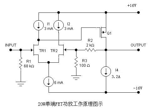
1. The working principle of the single-ended amplifier circuit is shown in the figure below: 
The differential circuit composed of TR1 and TR2 uses a constant current source circuit to stabilize the operation and improve the common-mode rejection ratio of the circuit. The output signal is a single-ended amplified output stage composed of Q3, and the constant current source I4 is used as the DC load of Q3. R1 determines the input impedance of the amplifier, and R2 and R3 are negative feedback loops, which determine the closed-loop gain of the amplifier.
2. Calculation of output power, supply voltage and quiescent current:
Taking the output power of 20W on a load of 4 ohms as an example, other output power and load impedance can be calculated separately or refer to Table 1.
According to P = I * I * R, I * I = P / R = 20/4 = 5, I = 2.236A. Where I is the effective value of the output current, so the maximum value of the output current IM = 1.414 * I = 1.414 * 2.236 = 3.16A. In actual production, it is 3.2A. This current value is the static current of the whole machine, which is I4 in Figure 1, which is provided by the constant current source of the circuit.
Because this circuit uses a drain output, there is a voltage gain at the final stage, so the power supply voltage utilization rate is high. For the convenience of calculation to take 0.8, the power supply voltage is required to be: VCC = (IM * R) /0.8=16V.
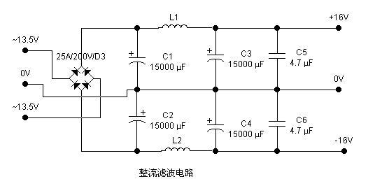
In order to reduce the cost, this circuit adopts the power supply form of bridge rectification and large-capacity capacitor filtering. According to the current and voltage relationship of the circuit: U2 = VCC / 1.2, so U2 = 16 / 1.2 = 13.3V, the actual production can be A transformer with a secondary voltage of 13.5V is used.
Because this machine is a single-ended pure Class A power amplifier circuit, it works in the state of maximum power consumption when it is turned on. The power consumption is: 2 * 16 * 3.2 = 102.4W. In order to make the circuit operation stable and reliable, the rated power of the power transformer should be 3-5 times the actual power consumption, so the rated power of the power transformer is 300-500W.
3. Selection of rectifier components and filter components: 
Due to the large operating current of this machine, the actual working mono is above 3A. In order to reduce the internal resistance of the power supply, the rectifier element uses a metal square bridge above 25A / 200V.
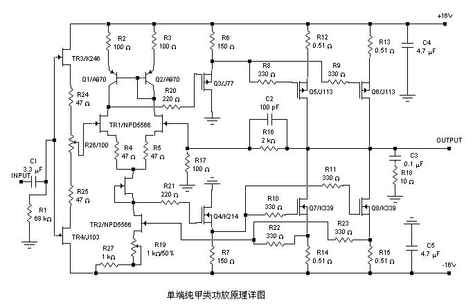
4. Brief introduction of circuit principle and selection of components 
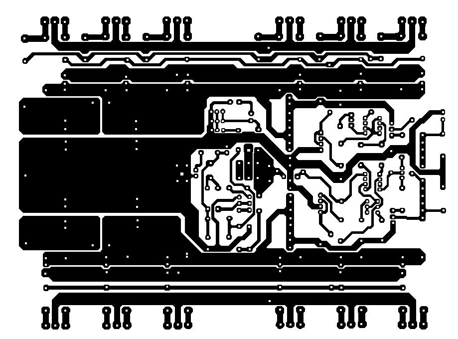
Five, printed board drawings for reference 


'+ data.username +'
Design and manufacture of 20W-50W single-ended FET pure class A power amplifier
Interesting and informative information and technical dry goods
Create your own personal electronic circle
Lock the latest course activities and technical live broadcast
comment
Publish