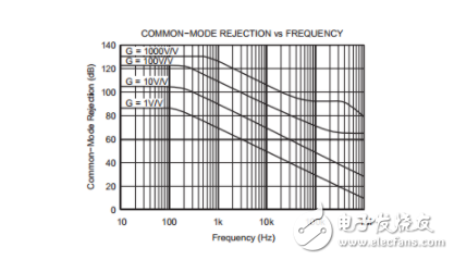
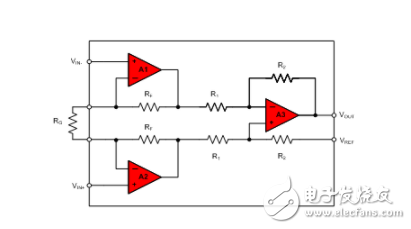
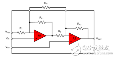
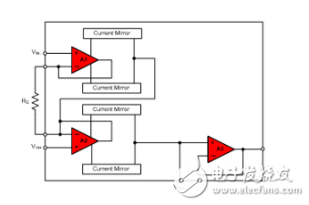
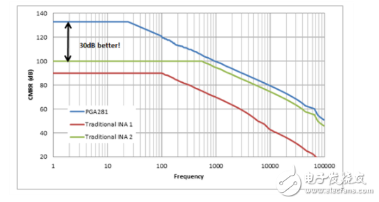
Not all structures are equal. Just as you wouldn't choose a single tool to build a house, you shouldn't assume that all instrumentation amplifiers (INAs) work best in all applications. Common mode rejection ratio (CMRR) and common mode rejection (CMR) measure the ability of a differential input amplifier (such as an op amp or INA) to reject a common input signal from two inputs. In other words, since the common mode voltage is different from that specified in the data sheet, a bias voltage appears at the input. In addition to the initial input offset voltage, this offset voltage is amplified by the differential gain of the device or circuit! The technical definition of CMRR is the ratio of differential gain to common mode gain. The measurement is made by changing the input common mode voltage and observing the change in the output voltage. This change value is referred to as an input by dividing by the gain and is considered to be an input offset voltage change. CMRR is usually reported in decibels (dB) for easy interpretation and comparison. There are no industry standards and CMRR and CMR are often interchanged. Because of the common mode gain, CMRR depends on several amplifier design factors, including: Design process variables: Source and drain resistance matching Gate-drain capacitance Forward transconductance Gate leakage current Output impedance of the tail current source Frequency change due to shunt capacitance of the tail current source The CMRR change in frequency is shown in the INA128 curve below. Figure 1: INA128 CMRR with a gain of 1, 10, 100, 1000V/V There are several different ways to create an INA, including: Triple Operational Amplifier INA: Differential amplifier with buffered input, such as INA826. For more information on differential amplifier topologies, check out my previous blog post: The CMRR you need to know - the instrumentation amplifier. This topology addresses the low impedance limit of the differential amplifier. The input stage is used to improve the signal-to-noise ratio and common mode rejection to gain differential voltage. The disadvantage is that the size is larger and the cost is higher. Figure 2: 3 Operational Amplifier INA Dual Operational Amplifiers INA: A simpler INA like the INA126, with few precision resistors and op amps to compete with. This translates into lower cost, smaller package and lower quiescent current. The drawback of the topology is the difference in noise gain between the two op amps. This allows the CMRR to degrade faster in frequency than the three op amps INA. Figure 3: Dual Operational Amplifier INA Special Topology INA: The emergence of new architectures has opened up more possibilities for the development of INA. Current mirror based designs, such as the PGA281, convert the input signal into a current. Current mode signal processing also suppresses common mode input voltage and power supply variations if the resistors are not precisely matched. Figure 4: Current Mirror INA Modern design techniques and process improvements have greatly improved CMRR at low gain and crossover frequencies, as seen in the INA PGA281 with programmable internal gain. Compared to traditional INAs, the PGA281 uses proprietary architecture technology and precision process matching to increase unity gain CMRR by 30dB. Figure 5: PGA281 CMRR vs unity gain frequency compared to traditional instrumentation amplifiers Eye fitting,Clevis Electric Power Fittings,High Quality Ball Eye Oval Insulator Fittings TAIZHOU HUADONG INSULATED MATERIAL CO.,LTD , https://www.thim-insulator.com
