Compared with the linear regulated power supply, the switching power supply has many advantages such as low power consumption, high efficiency, small size, light weight, and wide voltage regulation range. It has been widely used in computers and their peripheral equipment, communications, automatic control, and household appliances. And other fields.
But the outstanding shortcoming of the switching power supply is that it can produce strong electromagnetic interference (EMI). EMI signal has a wide frequency range and a certain amplitude. After conduction and radiation, it will affect the electromagnetic environment and cause interference to communication equipment and electronic products.
If not handled properly, the switching power supply itself will become a source of harassment. At present, the electromagnetic compatibility (EMC) of electronic products has been paid more and more attention. To suppress the EMI of switching power supplies, improve the quality of electronic products, and make them comply with EMC standards has become an issue of increasing concern for electronic product designers.
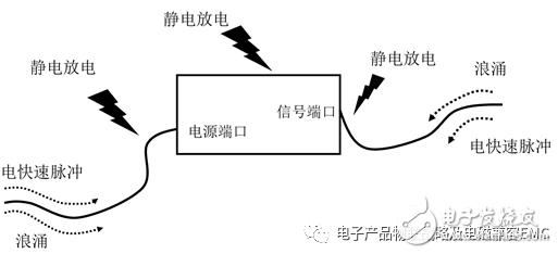
Let's first take a look at the interference of the external environment on the switching power supply mainly from the jitter of the power grid, lightning strikes, external radiation, etc.; as shown below:

1. Power supply noise?
2. Power reset?
3. Power output?
4. The power supply is damaged?
and many more.
Transient interference (EMS) can pose a threat to the equipment and cause problems with product functions and performance.
Later, we will explain the problem of switching power supply system EMS through PCB analysis;
The three major considerations of EMC for switching power supply system products can be solved by understanding and finding EMC.
1. signal source);
2. Structural design
3. Ground connection.

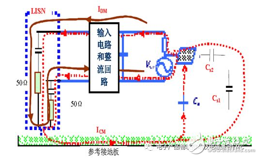
Current path analysis of conducted interference common mode and differential mode signals.
The switching power supply usually rectifies the power frequency alternating current into direct current, then turns it into high frequency through the control of the switch tube, and then outputs through the rectifier filter circuit to obtain a stable direct current voltage. Power frequency rectification and filtering use large-capacity capacitors for charging and discharging, high-frequency switching of switching tubes, and reverse recovery of output rectifier diodes. Very high di/dt and du/dt are generated during the work process, forming a strong surge current And peak voltage, it is the most basic cause of electromagnetic interference of switching power supply.
In addition, the driving waveform of the switch tube, the MOSFET drain-source waveform, etc. are all periodic waves that are close to a rectangular wave shape. Therefore, its frequency is MHz-level, with very high high-frequency harmonic components! These high frequency signals cause interference to the basic signals of the switching power supply, especially the signals of the control circuit.
Simply put: when the MOS tube is turned on in the switching power supply system, the current of the transformer inductance in the L and N loops rises linearly; when the MOS is turned off, the current in the L and N loops is quickly turned off; the current waveform of the loop at this time is a triangular wave; high frequency The harmonic component of the triangular wave current forms the differential mode interference of the system.
Spurious parameters affect the characteristics of the coupled channel
In the conducted disturbance frequency band (<30MHz), most of the coupling channels of the switching power supply disturbance can be described by a circuit network. However, any actual components in the switching power supply, such as resistors, capacitors, inductors, and even switching tubes, diodes, contain stray parameters, and the wider the frequency band studied, the higher the order of the equivalent circuit, so , The equivalent circuit of the switching power supply including the stray parameters of various components and the coupling between the components will be much more complicated.
At high frequencies, stray parameters have a great influence on the characteristics of the coupling channel, and the existence of distributed capacitance becomes a channel of electromagnetic disturbance. In addition, when the power of the switch tube is high, the collector generally needs to add a heat sink. The distributed capacitance between the heat sink and the switch tube cannot be ignored at high frequencies. It can form space-oriented radiation disturbance and power line conduction. Common mode harassment.
Simply put: when the high frequency band>1MHZ, the switching power supply system has distributed capacitance to the ground; the key signals of the system and the key traces have distributed capacitances to the ground; the distributed capacitance forms a common mode interference that returns to L and N to the ground. signal. At the same time, the loop of distributed capacitance forms radiation interference to space!
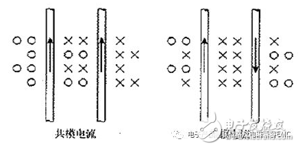
Radiation interferes with the magnetic field distribution of common mode and differential mode signals.

1. The magnetic field of the differential mode current is mainly concentrated in the loop area formed by the differential mode current.
The lines of magnetic force outside the loop area will cancel each other out;
2. The magnetic field of the common mode current is outside the loop area,
The direction of the magnetic field generated by the common mode current is the same, but the magnetic field strength is strengthened instead.
note:
An important basic concept about radiation is that current causes radiation, not voltage.
Radiation interferes with the field strength characteristics of common mode and differential mode signals.
1. Smaller common-mode current can produce high-intensity radiation;
2. Many factors can cause common mode current;
such as:
A. The common mode interference voltage is serially connected to the power grid-(part of our EMS simulation test);
B. Radiation interference (such as lightning, equipment arcs, nearby radio stations, high-power radiation sources) induces common mode interference on the signal line;
C. The ground voltage is different. That is to say, the difference in ground potential introduces common mode interference;
D. It also includes the influence of the internal wires of the equipment on the power cord.
Data result-40dB test data analysis:
Data1: A 20mA differential mode current,
At 30MHZ, a radiant electric field with an intensity of 100uV/m will be generated at a distance of 3m.
Data2: A common mode current of 8uA,
At 30MHZ, a radiant electric field with an intensity of 100uV/m will be generated at a distance of 3m.
A small common-mode current and a large differential current generate equal RF energy.
Reason: The common mode current cannot cancel the magnetic field lines in the RF return path.
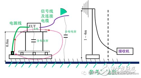
Analysis of electromagnetic field loops affected by distributed parameters of radiated interference system

The switching power supply system has distributed capacitance to the ground; the key signals of the system and the key traces have distributed capacitances to the ground; the common mode current flows through the layout and wiring through the signal lines of the system and the distributed capacitance of the cables to form a ground return to L, N Common mode interference signal. At the same time, the loop of distributed capacitance forms radiation interference to the space.
Among them, >30MHZ is the antenna receiving of radiation emission; that is, the common mode radiation generates electromagnetic field in space. At this time, after being received by the receiving antenna of the radiation disturbance test, then the external radiation disturbance of the product is formed.
Three major considerations on the EMC of electronic products.
A. Where is the signal (source);
B. Is the structure design like this?
C. Is there a better way to connect the ground?
Small computer system interface (SCSI) is an independent processor standard for system level interfaces between computers and intelligent devices (hard disks, floppy drives, optical drives, printers, scanners, etc.). SCSI is an intelligent universal interface standard.
In addition to SCSI, IDE is also a very common interface. From the point of view of ease of use, IDE is more suitable for ordinary users. In addition, personal computer users not only need to configure a few peripherals, but also do not require high speed. Therefore, it is more appropriate to choose IDE interface. In addition, IDE also has the characteristics of high performance price ratio and wide application. Although the SCSI interface has many incomparable characteristics, the price of the interface and its peripherals is too expensive to be borne by ordinary users, which determines the limitation of its actual use range.
1. The working mode of IDE requires the whole process participation of CPU. When the CPU reads and writes data, it can't perform other operations. In this case, in the multitask operating system of Windows 95 / NT, the system reaction will be greatly slowed down. The SCSI interface controls the data reading and writing operation completely through the independent high-speed SCSI card, so the CPU does not have to waste time to wait, which obviously can improve the overall performance of the system. However, IDE interface has also made great improvements to improve this problem. DMA mode can be used instead of PIO mode to read and write data. DMA channel is responsible for data exchange, which greatly reduces the CPU consumption. However, comparing the CPU utilization of SCSI and IDE, we can find that SCSI still has considerable advantages.
2. The scalability of SCSI is larger than that of IDE. Generally, each ide system can have two IDE channels, with a total of four IDE devices. The SCSI interface can connect 7-15 devices, much more than IDE, and the cable connected is far longer than ide.
3. Although the price of SCSI device is higher, compared with IDE, the performance of SCSI is more stable, durable and reliable.
SCSI Solder Type Section
ShenZhen Antenk Electronics Co,Ltd , https://www.antenkwire.com