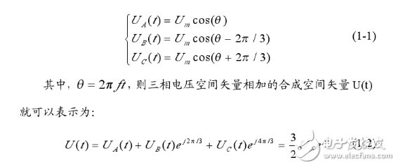
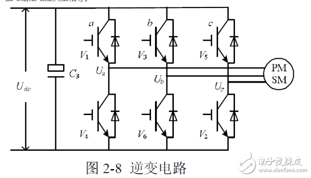
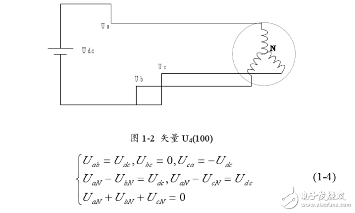
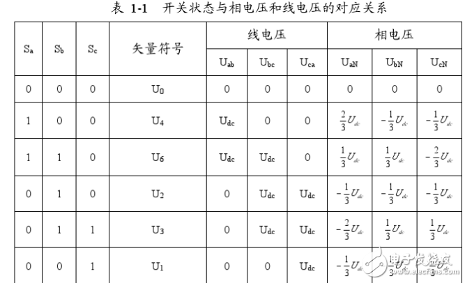
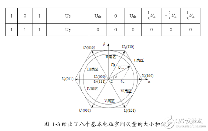
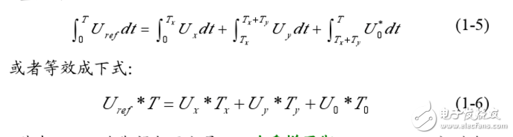
Space Vector Pulse Width Modula (TI) is a new technology that has been applied to inverters, UPS, and reactive power compensators. In recent years, with the development of technical upgrading and upgrading of large-scale heavy industry, the demand for high-power, high-quality inverters is increasing day by day. This situation is particularly prominent in China. The development of power electronics technology, microelectronics technology and control theory has prepared conditions for the maturity of inverter technology. Advanced SVPWM technology has emerged in this environment. The SVPWM algorithm of the inverter is closely related to its topology. Therefore, the corresponding control algorithm must be selected according to the different topology of the inverter. SVPWM is a relatively novel control method developed in recent years. It is a pulse width modulated wave generated by a specific switching mode composed of six power switching elements of a three-phase power inverter, which can make the output current waveform as close as possible to the ideal one. Sinusoidal waveform. The space voltage vector PWM is different from the traditional sinusoidal PWM. It starts from the overall effect of the three-phase output voltage and focuses on how to make the motor obtain the ideal circular flux linkage. Compared with SPWM, the SVPWM technology has a small harmonic component of the winding current waveform, which reduces the torque ripple of the motor, and the rotating magnetic field is closer to a circular shape. Moreover, the utilization of the DC bus voltage is greatly improved, and it is easier to digitize. PAM is the abbreviation of PulseAmplitudeModulaTIon in English. It is a modulation method that changes the pulse amplitude of pulse train according to a certain rule to adjust the output value and waveform. It is to change the modulation pulse mode and pulse width on the basis of PWM. The time duty cycle is arranged in a sinusoidal rate so that the output waveform is properly filtered. The theoretical basis of SVPWM is the principle of average equivalent, that is, by combining the basic voltage vectors in one switching cycle, the average value is equal to the given voltage vector. At some point, the voltage vector is rotated into a region that can be derived from different combinations of two adjacent non-zero vectors and zero vectors that make up the region. The action time of the two vectors is applied multiple times in one sampling period, thereby controlling the action time of each voltage vector, so that the voltage space vector is rotated close to the circular trajectory, and the actual magnetic flux generated by the different switching states of the inverter goes. The ideal flux circle is approximated, and the switching state of the inverter is determined by the comparison result of the two, thereby forming a PWM waveform. The inverter circuit is shown in Figure 1-1. Let the voltage on the DC bus side be Uas, and the three-phase voltage of the inverter output be UA, Ug, Uc, which are respectively added to the three-phase plane stationary coordinate system with spatial difference of 1200, and three voltage space vectors UA can be defined. (t).Ug(t).Uc(t), whose direction is always on the axis of each phase, and the magnitude changes with sinusoidal law over time, with a time phase difference of 120. Assuming Um is the phase voltage rms and f is the power frequency, there are: It can be seen that U(t) is a rotating space vector whose amplitude is 1.5 times the peak value of the phase voltage, Um is the phase voltage peak, and the space vector is rotated at a constant speed in the counterclockwise direction with the angular frequency c=2nf, and the space vector The projection of U(t) on the three-phase coordinate axes (a, b, c) is a symmetric three-phase sinusoid. Since there are 6 switching tubes in the three-phase bridge arm of the inverter, in order to study the space voltage vector of the inverter output when the upper and lower bridge arms are combined, the special switching function Sx(x= a, b, c) is: There are a total of eight possible combinations of (Sa.Sb.Se), including 6 non-zero vectors U1: (001). U2: (010). U3 (011). U4 (100). U5 (101). U6 ( 110). And two zero vectors Uo(000).U7(111), the following is an example of one switch combination, assuming Sx(x= a,b,c)= (100), at this time Solving the above equation can be obtained: Uan=2Uj/3, Ubn=-Ua/3, Ucn=-Ua/3. Similarly, the space voltage vectors under various other combinations can be calculated, as follows: The non-zero vectors have the same amplitude (modulo length is 2Ua/3), the adjacent vector spacing is 60*, and the two zero vector amplitudes are zero, centered. In each sector, select two adjacent voltage vectors and zero vectors, and synthesize any voltage vector in each sector according to the principle of volt-second balance, namely: Where Uref is the expected voltage vector; T is the sampling period; Tx, Ty, and TO are the action times of the two non-zero voltage vectors Ux.Uy and zero voltage vector UO respectively in one sampling period; wherein UO includes UO and U ) Two zero vectors. The meaning of equation (1-6) is that the integral effect value generated by the vector Uref in the T time and the sum of the integral effects of the UX, Uy, and UO generated in the time Tz.Ty.To are the same. Since the three-phase sinusoidal voltage synthesizes an equivalent rotational voltage in the voltage space vector, its rotational speed is the input power angular frequency, and the equivalent rotational voltage trajectory will be a circular shape as shown in Figure 1-3. Therefore, to generate a three-phase sine wave voltage, the above voltage vector synthesis technique can be utilized. On the voltage space vector, the set voltage vector is started from the U4 (100) position, and each time a small increment is added, each small increase. The set voltage vector can be synthesized by using two adjacent non-zero vectors and zero voltage vectors in the region, so that the obtained set voltage vector is equivalent to a voltage space that smoothly rotates on the voltage space vector plane. Vector, thereby achieving the purpose of voltage space vector pulse width modulation. RAM/RFM Middle Frequency Water Cooled Capacitors RAM/RFM Middle frequency water cooled capacitors Water Cooled Capacitors,Medium Frequency Capacitor,Intermediate Frequency Capacitors YANGZHOU POSITIONING TECH CO., LTD. , https://www.cnfudatech.com