Runway Speaker,Runway Micro Speaker,Track Runway Speaker,Outdoor Runway Speakers NINGBO SANCO ELECTRONICS CO., LTD. , https://www.sancobuzzer.com
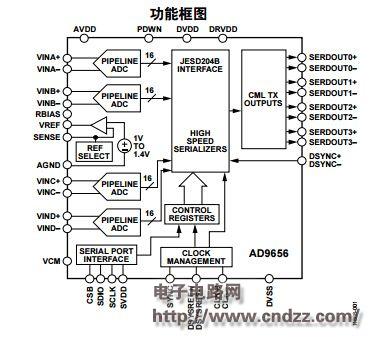
It also supports independent shutdown of each channel; typical power consumption is less than 2 mW when all channels are disabled. The ADC's built-in features enable optimal device flexibility and lowest system cost, such as programmable output clock and data alignment, digital test code generation, and more. The available digital test codes include built-in fixed and pseudo-random codes, as well as user-defined test codes that are input via the Serial Port Interface (SPI).
AD9656 product features:
1. An on-chip phase-locked loop (PLL) allows the user to provide a single ADC sample clock. The corresponding JESD204B data rate clock is generated by multiplying the PLL by the ADC sample clock.
2. The configurable JESD204B output module supports a sampling rate of up to 6.4 Gbps per channel.
3, JESD204B output module supports 1/2/4 channel configuration
4. Low power consumption: 198 mW per channel for 2 channels and 125 MSPS.
5, SPI control provides rich and flexible features to meet the needs of a variety of specific systems
AD9656 application:
1, medical imaging
2, high speed imaging
3. Orthogonal radio receiver
4. Diversity radio receiver
5, portable test equipment AD9656 internal function diagram:  Figure 1: AD9656 internal function diagram AD9656 typical differential clock diagram:
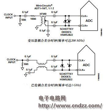
  Figure 2: AD9656 Typical Differential Clock Diagram The AD9656 has a flexible clock input structure. A CMOS, LVDS, LVPECL or sine wave signal can be used as its clock input signal. Regardless of which signal is used, clock source jitter must be considered (see the jitter considerations section). Figure 2 shows two preferred methods for clocking the AD9656 (up to 1 GHz before the internal clock is divided). A single-ended signal from a low-jitter clock source can be converted to a differential signal using an RF transformer or RF balun. RF balun configurations are recommended for clock frequencies from 125 MHz to 1 GHz; RF transformer configurations are recommended for clock frequencies from 40 MHz to 200 MHz. A Schottky diode across the transformer/balun secondary winding limits the clock signal input to the AD9656 to approximately 0.8 V peak-to-peak (see Figure 2).
AD9656 Datasheet: Download more schematics and PCB source code now: