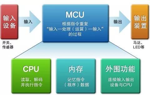
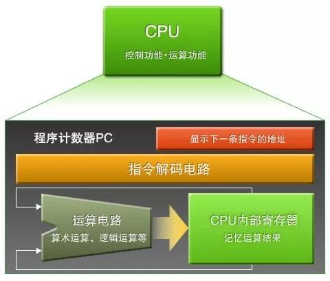
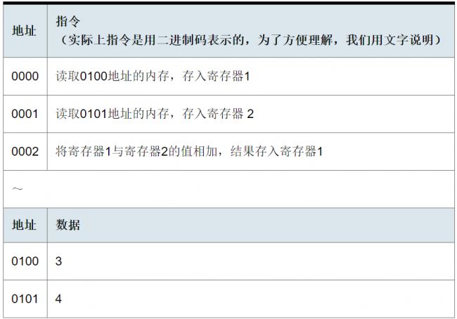
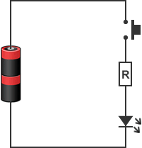
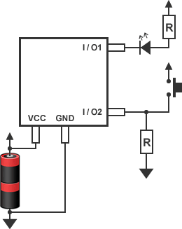
Today, the basic structure and working principle of the SCM are first learned, as well as peripheral functional circuits. Then, the operation of an actual SCM is challenged. SCM is the brain that controls electronic products Today, many appliances in our lives use a single-chip microcomputer. For example: mobile phones, televisions, refrigerators, washing machines, and children's toys where the LED flashes when the switch is pressed. So what exactly does the microcontroller do in these appliances? The single-chip microcomputer is the key to the operation of these electrical appliances, and it is the directing hardware operation. For example: receiving the input signal of the button or button, according to the pre-programmed program, command the motor and LCD peripheral function circuit action. So, how is the microcontroller built? As shown in Figure 1. The SCM consists of CPU, memory, and peripheral functions. If the microcontroller is like a human, then the CPU is responsible for thinking, the memory is responsible for memory, the peripheral function is equivalent to the visual sensory system and the nervous system that controls the hands and feet. Figure 1: Components of the Microcontroller Although we say that the CPU is equivalent to the human brain, it cannot be consciously and spontaneously thought like the human brain. The CPU can only read and execute instruction combinations (programs) previously stored in memory. Of course, the instructions executed by the CPU are not difficult commands such as "walk" and "speech", but rather very simple instructions, such as "reading data" from somewhere in memory or "writing" data to memory. Somewhere, or add, multiplication, and logic operations. However, the combination of these simple instructions can achieve many complex functions. Think of the CPU Let us understand the role of the CPU from its composition, as shown in Figure 2. Figure 2: The role of the CPU The program counter CPU needs to know where to store the instruction to be executed when it reads the instruction. This position information is called an address (equivalent to a home address). The program counter (PC) is the register that stores the address. Usually, the PC is designed in increments of 1, that is, when the CPU executes an instruction in address 0000, the PC automatically increments by one and becomes the 0001 address. Each execution of a PC will automatically increment 1 and point to the address of the next instruction. It can be said that the PC determines the order of program execution. â—‡ Instruction Decode Circuit The instruction decode circuit interprets the meaning of instructions read from memory. The arithmetic circuit operates based on the decoding result. Specifically, the instruction decoding circuit is a decoding circuit that we learned in “Introduction to Digital Circuits (2)â€, but the circuit structure is slightly more complicated. Therefore, the instruction decoding circuit works from being symbolized (encrypted). In the instruction, restore the instruction. The arithmetic circuit operation circuit is also referred to as an Arithmetic and Logic Unit (ALU) and is a circuit that performs an arithmetic operation. It can perform arithmetic operations such as addition and multiplication as well as logical operations such as AND, OR, and BIT-SHIFT. The operation is performed under the control of the instruction decoding circuit. The composition of the operating circuit is usually more complicated. â—‡ CPU internal registers The CPU internal registers are the places where temporary information is stored. There are general-purpose registers that store the operands and results, as well as some special registers, such as flag registers that store arithmetic flags. In other words, when an arithmetic circuit performs an operation, it does not directly operate in a memory, but copies data in a memory to a general-purpose register and performs calculation in a general-purpose register. How does the CPU work? Let us illustrate the operation of the CPU through a concrete operation 3+4. Assume that the program and data stored in the memory are as follows. â—‡ Step 1: When the program is executed, the CPU reads the instruction at the address 0000 pointed to by the current PC (this operation is called instruction reading). After decoding by the decoding circuit, this instruction means "read the contents of the 0100 address and then save it to the register 1". The CPU then executes the instruction, reads data from address 0100, and stores it in register 1. Register 1: 0→3 (changes from 0 to 3) Since one instruction was executed, the value of PC becomes 0001 â—‡ Step 2: Since the value of PC is 0001, the CPU reads the instruction in the 0001 address. After being decoded by the decoding circuit, the CPU executes the instruction. Then add 1 to the PC. Register 2:0→4 (change from 0 to 4) PC:0001→0000 â—‡ Step 3: Since the PC value is 0002, the CPU reads the instruction from the 0002 address and sends it to the instruction decoding circuit. The decoding result is: Add register 1 and register 2 and store the result in register 1. Register 1:3→7 PC: 2→3 Then the result 7 of 3+4 is stored in register 1, and the addition operation ends. The CPU is like this, processing each simple instruction in turn. Memorable memory The memory is the memory device of the one-chip computer, mainly memorize the program and data, generally divide into ROM and RAM two kinds of categories. â—‡ROM ROM (Read Only Memory) is short for read-only memory. Data stored in ROM cannot be deleted or lost due to power failure. The ROM is mainly used to save user programs and constants that remain unchanged during program execution. Most Renesas microcontrollers use flash memory as ROM. This is because the flash memory can not only be like a ROM, but it will not lose data even if it is turned off, but it also allows modification of data. RAM RAM (Random Access Memory) is an abbreviation for random read/write memory. You can read and write data at any time, but after shutdown, the data saved in RAM also disappears. Mainly used to store variables in the program. In single-chip microcomputers (*1), SRAM is often used as internal RAM. SRAM allows high-speed access, but the internal structure is too complex to achieve high-density integration and is not suitable for large-capacity memory. In addition to SRAM, DRAM is also a common RAM. The structure of the DRAM is relatively easy to achieve high-density integration and, therefore, has a larger capacity than the SRAM. However, it is difficult to install high-speed logic circuits and DRAMs on the same chip. Therefore, they are rarely used in single-chip microcomputers and are basically used as peripheral circuits. (*1) Single-chip microcomputer refers to the CPU, ROM, RAM, oscillation circuit, timer, and serial I/F integrated in one LSI microprocessor. The main peripheral circuits of some systems are further configured on the basis of single-chip microcomputers, and the formed large-scale integrated circuits are called system LSIs. "Why use SCM..." Why do many electronic devices use MCUs? Let's use a circuit that lights an LED as an example. As shown in Figure 3, a circuit that does not use a microcontroller is a simple circuit that consists of LEDs, switches, and resistors. Figure 3: LED circuit without a microcontroller The circuit using a microcontroller is shown in Figure 4. Figure 4: LED circuit diagram for installing a microcontroller Obviously, the use of a single-chip circuit is much more complicated, and the design of the circuit takes more effort and money. It seems that there is no advantage in using a microcontroller. However, it is still too early to draw conclusions. What if we let this circuit do some more complicated operations? For example, if you want the LED to turn on or off after a certain period of time after pressing the switch, then for a circuit with a microcontroller, you only need to change the program in the microcontroller, and you do not need to change the original circuit. On the other hand, for a circuit without a microcontroller, it is necessary to add a timer IC in the element circuit or a logic circuit with a standard logic IC and an FPGA to realize this function. That is, circuits with a microcontroller are obviously easier to implement when changing and adding new features. This is the reason for the use of microcontrollers in electrical equipment. SCM can be a convenient thing! We are manufacturer/supplier of USB flash drive from China,who offer 100% real original capacity to the world buyers.You can get high quality of USB flash drive from us with custom logo,and also help you build your own brand of USB flash drive 2.0 3.0 with reputation.Capacity from 2MB,8MB,64MB,128MB to 8GB 16GB 32GB 64GB 128GB and 256GB(Biggest real capacity can be 512GB).We mainly offer OEM /ODM service,and offer USB flash drive without logo or with your logos. Usb Flash Memory,Usb Flash Drive 32Gb,Usb Flash Drive Custom,Usb Flash Drive 3.0,USB Disk,Pendrive,USB key Shenzhen Konchang Electronic Technology Co.,Ltd , https://www.konchangs.com