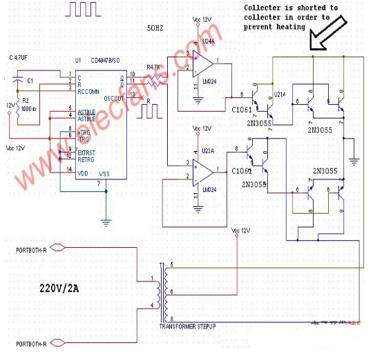
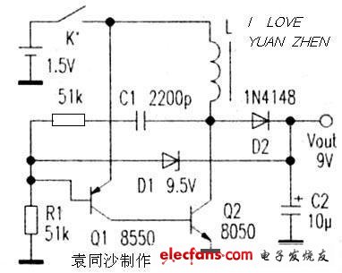
This DC 12V to 220V AC inverter circuit can be converted to 12V DC to 220V AC. CD4047 is used to generate square waves. The basic formula is P = VI between the input and output transformers, input power = output power. Therefore, the transformer is 12V to 220 volts, but the input winding must be able to withstand 20A. C1 is the role of positive feedback. When Q2 turns on, the positive feedback of C1 causes Q2 to quickly enter the saturation region. Then C1 discharges and reverses charging. As the base potential of Q1 increases, the base current of Q2 also decreases, and the current on L1 rises continuously. When it reaches a large enough Q2 to exit saturation, Q2 collector potential Raise, the positive feedback of C1 is given to the base of Q1 to increase the potential, so that Q1, Q2 will immediately return to the cut-off area. Q1 is turned on again, and it is necessary to recharge the R1 and C1 to lower the base potential of Q1. It takes a long time, so the charging time of the circuit L1 is usually much longer than the discharge (including waiting for recharging). Time. When D1 is connected, the output voltage is too high, which will affect the charging and discharging of C1, resulting in shorter on-time of Q1 and Q2 and longer waiting time after discharge. As can be seen from the above analysis, the operating frequency of this circuit is related to both R1 and C1. It is also affected by L1, but it has little effect. The driving ability of this circuit is related to the value of R1, L1 and the amplification factor of Q1 and Q2. This circuit is easy to start, and the conditions for no vibration are: R1 is relatively small. After Q1 and Q2 are turned on, C1 reverse charging is completed, and Q1 current reaches the minimum value. If Q2 is still in the saturation region (the internal resistance of L1 limits the collector current of Q2 to rise further), this It consumes a lot of power and the circuit stops. Transparent Led Film Screen P6 Good effect: using non-linear point-by-point correction technology, the text is clearer and the sense of hierarchy is stronger; strong reliability: using distributed scanning technology and modular design technology, higher reliability and stability; diverse display modes: supporting multiple Various display modes; easy to operate: the edited contents of the computer are sent to the system control card, and the edited contents can be displayed, and the system operation is very convenient. Transparent Led Film Screen P6,Flexible Led Display Screen,Indoor Led Display Screen,Transparent Indoor Led Screen Display Guangdong Rayee Optoelectronic Technology Co.,Ltd. , https://www.rayeeled.com

The simplest transformer circuit diagram (acquisition of the AC inverter / oscillation boost circuit schematic)
The simplest transformer circuit diagram (1) DC 12V to 220V AC inverter circuit diagram (500W)