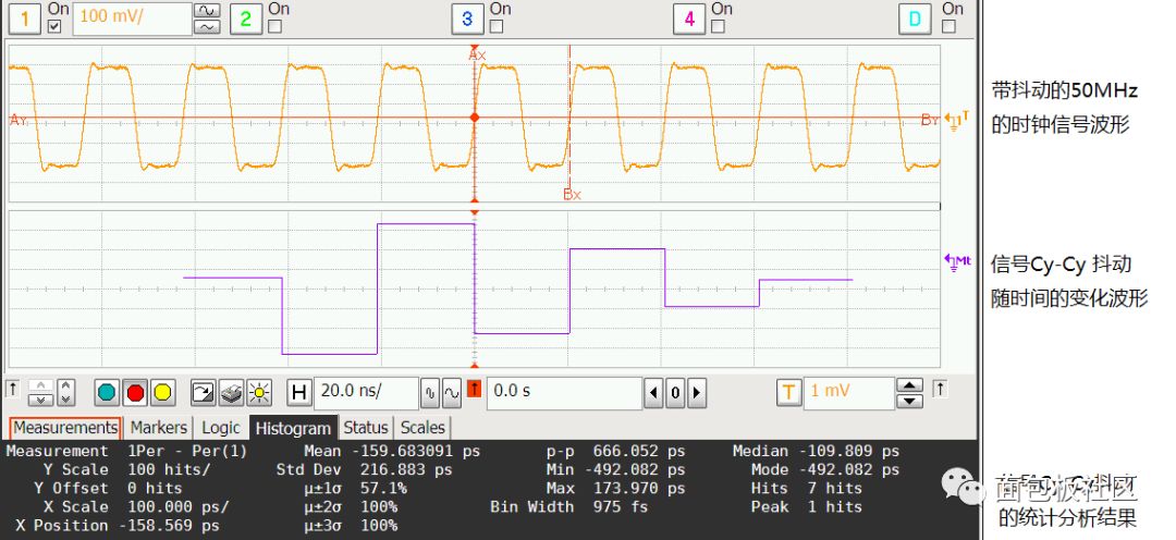
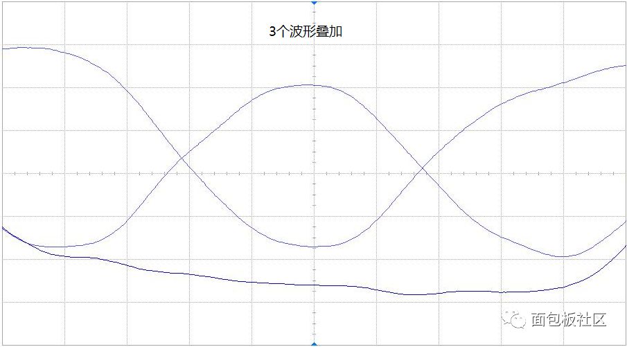
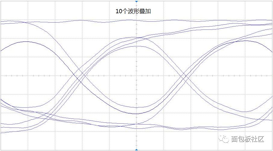
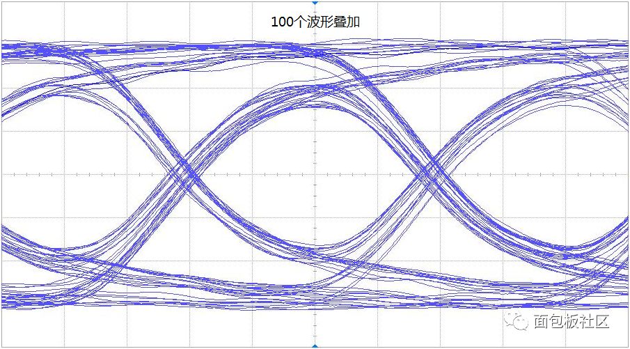
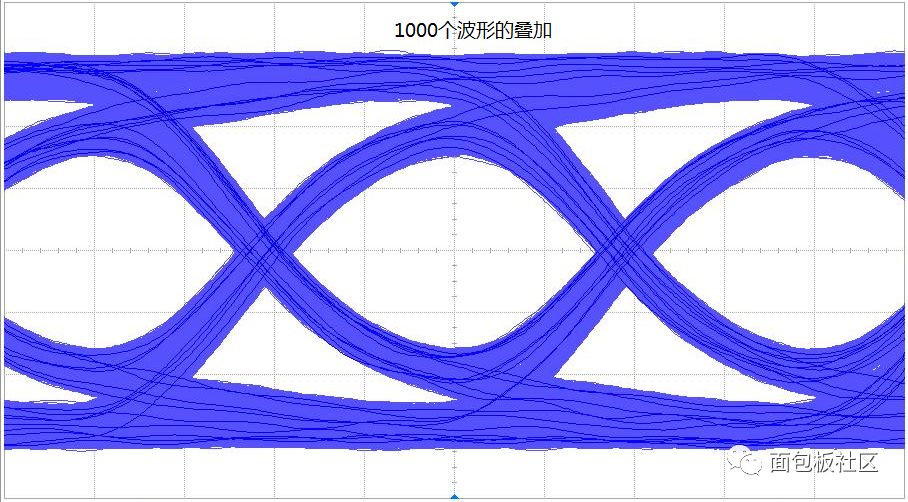
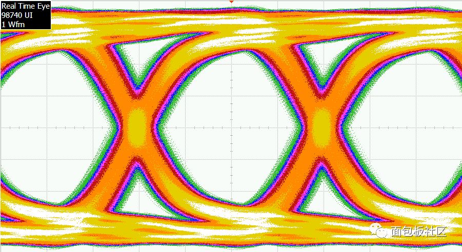
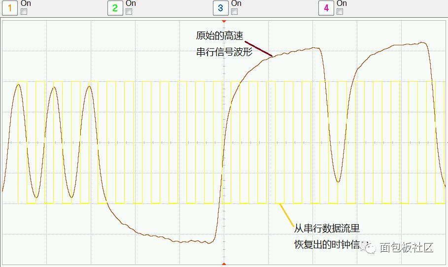
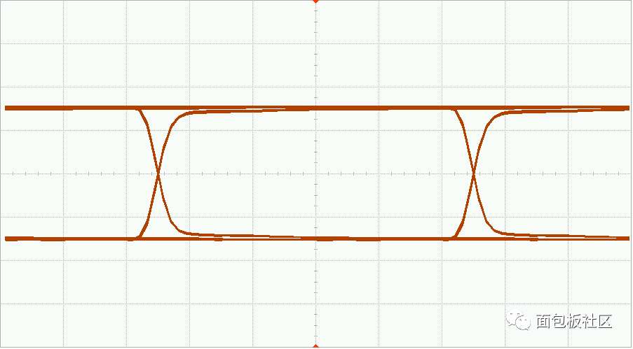
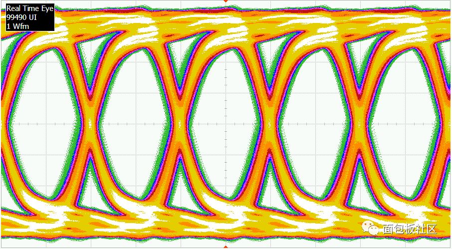
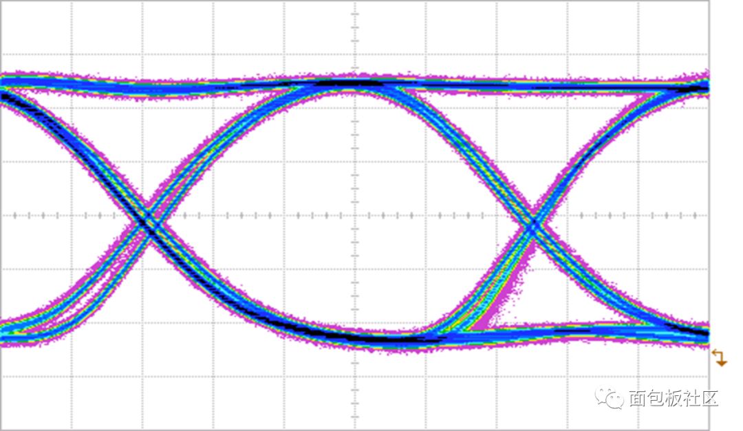
Waveform parameter test is the most commonly used measurement method for digital signal quality evaluation. However, with the increase of digital signal rate, measurement methods based solely on amplitude, rise time, and other waveform parameters become less and less applicable. For example, for a 5Gbps signal in the figure below, the amplitude, rise time, and pulse width of the signal at different locations are different because of the loss of the transmission channel. The results obtained by different operators at different positions of the waveform are also different. Therefore, we must use other methods to evaluate the quality of the signal. The most commonly used method for high-speed digital signals is the eye-diagram measurement method. The so-called eye diagram is actually a statistical distribution chart formed naturally by superposition of the data bits at different positions of the high-speed digital signal according to the interval of the clock. The following figures show the formation of the eye diagram. We can see that as the number of superimposed waveforms increases, the digital signal gradually forms a shape resembling an eye. We call this figure an eye diagram. When the digital signal is superimposed to form an eye diagram, in order to facilitate distinguishing the probability of the signal appearing at different positions, the signal of the color persistence pattern is observed more often. Color afterglow is the probability that the signal appears in different positions on the screen with the corresponding color, so you can intuitively see the signal noise, jitter and other distribution. The following figure shows an eye diagram with color persistence. For the eye diagram concept, the following points are more important: The eye diagram is a superposition of waveforms: The eye diagram measurement method is not to measure waveform parameters of a single waveform or a specific bit position, but to superimpose as many waveforms or bits as possible so that the statistical distribution of the signal can be seen. Only the worst signal satisfies our most basic requirements for the signal, only that the signal quality is acceptable. Waveforms need to be superimposed on a clock-based basis: The eye diagram is a superposition of multiple waveforms or bits, but this superposition is not arbitrary and is usually based on a clock. For many parallel buses, since most of them have a dedicated clock transmission channel, the clock channel is usually used as a trigger to superimpose the waveform of the data signal to form an eye diagram. General oscilloscopes have this function. For many high-speed serial bus signals, since the clock information is embedded in the data stream, the measurement equipment needs to have a corresponding clock recovery function (possibly hardware or software) and can be extracted from the data stream first. A clock is output, and then the data bits are superimposed on this clock to form an eye pattern. Therefore, eye diagram testing of many high-speed serial digital signals usually requires the oscilloscope or measurement device to have a corresponding clock recovery function. The following figure is an example of software clock recovery for serial data streams. The true eye diagram is superimposed on the basis of the clock: the fundamental purpose of the eye diagram measurement is to determine the establishment/hold of the data signal relative to its clock signal (which may be a dedicated clock channel or embedded clock information). The parameters such as the time window and the signal amplitude at the time of sampling meet the requirements of the standard, so the eye pattern measurement must be based on the reference clock as the basis for signal superposition. Sometimes natural superposition with the edge trigger of the data signal itself can also form an eye-like shape, but this is not a true eye pattern. Eye diagram of low-speed signal: Many buses with less high speed can also do eye measurement, but due to the wide data bits, the proportion of rise time to data bit width is very small, so the eye diagrams of some low-speed digital signals may be compared. Founder, or more structured, does not look like eyes, but it is still an eye diagram in terms of physical meaning. The following figure is an example of an eye diagram formed by the superposition of a low-speed digital signal. The number of waveforms or bits that need to be superimposed in an eye-pattern measurement: In an eye-pattern measurement, the number of superimposed waveforms or bits is not the same, and there may be subtle differences in the resulting eye-diagram results. Due to the existence of random noise and random jitter, the more waveforms or bits that are superimposed, the smaller the degree of eye opening will be, and the more measurable the worst case, the longer the corresponding test time will be. In order to make a compromise between the reliability of the measurement results and the measurement time, some standards may stipulate that the eye diagram measurement needs to superpose the waveform or the number of bits. For example, it is necessary to superimpose 1000 waveforms or superpose 1M bits. Choice of eye position: When the digital signal is waveform or bit superimposed, it forms not just an eye diagram, but a continuous eye diagram. If the number of superimposed waveforms or bits is sufficient, these eye diagrams are very similar, so any one of them can be measured. The figure below shows the multiple consecutive eye patterns formed by the superposition. It can be seen that each eye pattern is very similar. In general, for the convenience of measurement, the time base scale is generally adjusted so that only a complete eye pattern is displayed on the screen. Another thing to note is that when the eye pattern is measured, the device under test only sends data streams that are as random as possible to form a true eye pattern. If the data in the data stream is a long 0, long 1, clock pattern, or some other rule The pattern may not form an eye pattern or the formed eye pattern is incomplete. The following figure is an incomplete eye diagram, missing the long 0 pattern in the data stream.
Thyristor module is one of the most commonly used semiconductor devices because of its small size, simple structure and strong function.This device has been widely applied in various kinds of electronic equipment and electronic products, used as a rectifier, inverter, frequency, voltage regulator, contactless control of motor speed, motor excitation, non-contact switch and the power control, etc.
Thyristor Module,High Current Thyristor Module,Air Cooling Thyristor Module,Standard Voltage Thyristor Module YANGZHOU POSITIONING TECH CO., LTD. , https://www.pst-thyristor.com