0 Preface
As an important part of the vehicle, the electrical system is responsible for power supply, vehicle start, vehicle body protection, important parameter information indication, and the provision of lighting and sound. The realization of each function will directly affect the performance of the vehicle. . Due to the randomness of electrical equipment failure, it is necessary to conduct a general survey of the technical status of the vehicle before and after the vehicle is used to facilitate the management and use of the vehicle. However, implementing system accurate performance tests for multiple electrical devices of a vehicle takes a long time, which is difficult to achieve in the base level test process, and is also completely unnecessary. At the same time, it is completely unnecessary. In this paper, aiming at the task-oriented equipment performance census, a vehicle electrical system non-disassembly rapid technical condition detection method is designed, and the overall performance of the vehicle electrical system is evaluated according to the test results, and data support is provided for vehicle utilization.
1 Overall test plan
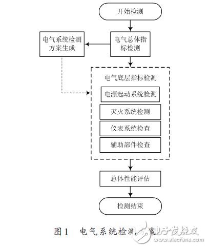
Aiming at the demand of rapid technical condition detection, this paper proposes a task-oriented hierarchical test scheme, which firstly performs the overall indicator detection. On this basis, the underlying detection scheme is determined according to the task, and the detection is implemented. The detection scheme is shown in Figure 1. The overall indicator detection mainly through the observation of the instrumentation, the empirical judgment of the starting process, preliminary judgment of whether the vehicle power system, starting system, and instrumentation of the tested vehicle have obvious faults, complete the basic information collection of the vehicle, and give a preliminary evaluation of the vehicle performance. Provide basic information for the determination of the underlying test plan.

The underlying indicator detection determines the detection schemes of each subsystem based on the basic information provided by the overall indicator detection, the historical record of the vehicle, and the requirements of the vehicle support task, and comprehensively applies various means such as visual inspection, manual inspection, and instrument testing to each electrical component. The technical status of the system is tested in a hierarchical and focused manner, and the status descriptions of each subsystem are given to provide information support for vehicle specific performance evaluation.
2 choice of test methods
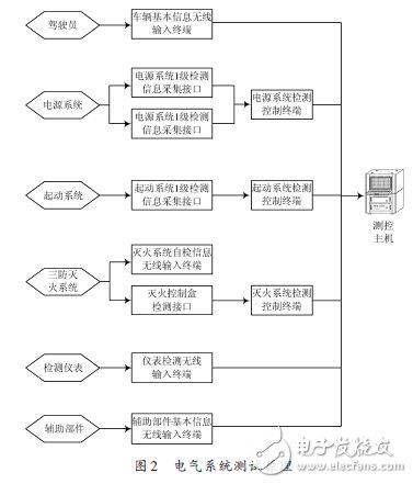
The subsystems of the electrical system are relatively independent and the test methods are different. Therefore, the system adopts a common distributed node design, and different test terminals are selected according to different tested subsystems. Considering that the test time requirements are short and targeted, it is necessary to select and optimize the test methods and test levels. The device under test that can directly pass the observation and test performance test requires that the test method be simplified as much as possible, especially the subsystem with self-test function, and try to use its self-test function to complete the test. For the system that is cumbersome to detect and difficult to install, the system can be stratified by the system. First, the first-level parameter test is performed. If the level 1 parameter does not meet the requirements, the next-level parameter check is performed.
According to the above rules, it is finally determined that the basic information collection, the fire-fighting system self-test, the instrument system detection, and the auxiliary component detection are directly implemented manually by the measurement and control personnel, and are transmitted to the measurement and control host through the PDA wireless input terminal. The power system detection, starting system detection, and fire extinguishing system component level testing adopt special detection and control terminals, and have a special detection interface circuit to realize distributed detection of subsystems. The detection results are transmitted to the measurement and control host through the data bus.
The test principle is shown in Figure 2.

Optical Line Terminal (OLT)
POE (Power Over Ethernet) refers to the use of IP-based terminals (such as IP phones, wireless LAN access points AP, network cameras) without any changes to the existing Ethernet Cat.5 cabling infrastructure. Etc.) The technology that can provide DC power for such devices while transmitting data signals is a switch that supports Power over Ethernet.
POE is also known as a power supply system based on local area network (POL, Power over LAN) or Active Ethernet (Active Ethernet), sometimes also referred to as Power over Ethernet for short. This is the use of existing standard Ethernet transmission cables to transmit data and data at the same time. The latest standard specification of electric power, and maintains compatibility with existing Ethernet systems and users. The IEEE 802.3af standard is a new standard based on the POE of the Ethernet power supply system. It adds related standards for direct power supply through the network cable on the basis of IEEE 802.3. It is an extension of the existing Ethernet standard and the first international standard for power distribution. standard.
IEEE began to develop the standard in 1999, and the earliest participating vendors were 3Com, Intel, PowerDsine, Nortel, Mitel and National Semiconductor. However, the shortcomings of this standard have been restricting the expansion of the market. Until June 2003, the IEEE approved the 802.3af standard, which clearly stipulates the power detection and control items in the remote system, and connects routers, switches, and hubs to IP phones, security systems, and wireless LANs through Ethernet cables. The method of power supply for points and other equipment is regulated. The development of IEEE 802.3af includes the efforts of many company experts, which also allows the standard to be tested in all aspects.
The IEEE 802.3at standard was formulated in 2005 and promulgated in 2009. The 802.3at standard output power can reach 30W, and the available power at the receiving end is 25.5W.
The IEEE 802.3 working group and various manufacturer alliances launched POH-POWER OVER HDBASET in the industry at the end of 2012.
Using the current 4-Pair four-pair wire technology plus, the bilateral power supply can reach 60-100W power, which can be achieved by using 5 or 6 types of wires. It is used in high-definition video promotion to supply power to 42" LED TVs. According to the new regulations in 2010, the power consumption of 42" LED TVs needs to be less than 70W.
Ethernet Poe Switches,Din Rail Mount Switch,Gigabit Din Rail Poe Switch,Managed Port Industrial Switch
Shenzhen Scodeno Technology Co.,Ltd , https://www.scodenonet.com