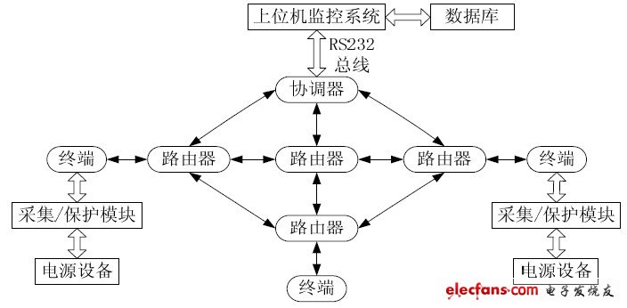
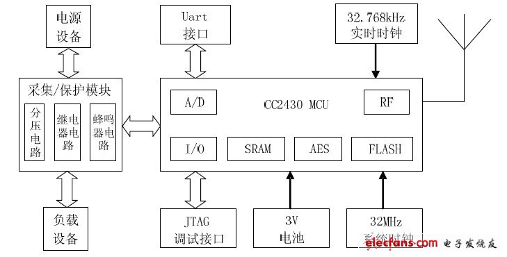
Abstract: Aiming at the shortcomings of the inconvenient wiring and low flexibility of the wired connection commonly used in current sensor networks, a method for real-time monitoring system based on ZigBee wireless network is proposed. The method of using CC2430 chip to build the system hardware platform and the software design process of each node protocol stack are introduced. Finally, the use of LabWindows / CVI to make the host computer interface is introduced. Finally, the wireless network is used to monitor the power supply. Experiments show that the system can collect real-time data of the power supply voltage of nodes in the ZigBee wireless sensor network. 0 Preface Traditional power supply monitoring systems mostly use wired connection. When there are many monitoring nodes, there are problems such as installation difficulties, complicated wiring and inconvenient maintenance. Using the wireless sensor network based on ZigBee technology to build this power monitoring system can solve the above problems. Now introduces the working principle of ZigBee technology and the design of real-time monitoring system. The ZigBee protocol stack structure is composed of physical layer, MAC layer, network layer and application layer. The ZigBee standard stipulates that all ZigBee network nodes are divided into three types: Coordinator, Route, and End Device. Regardless of the topology used by the ZigBee network, the network will automatically select a better routing path as the data transmission channel according to the ZigBee protocol algorithm to improve communication efficiency. 1 Monitoring system design 1.1 System structure design The block diagram of power supply voltage monitoring system based on ZigBee wireless network is shown in Figure 1. Figure 1 System structure The terminal node collects the voltage data of 0 ~ 30 V of the power supply device through the collection / protection module, and sends it to the coordinator node through the router node. At the same time, it also receives the control commands of the coordinator and processes accordingly; Data transfer to ensure that the data exchange between the coordinator node and the terminal node is correct, increasing the coverage of the ZigBee network; on the one hand, the coordinator node receives the power voltage data collected by the terminal node and sends the data to the host computer through the serial port, On the other hand, it receives the command information from the host computer and sends it to the corresponding terminal node; the host computer manages the status information of the monitoring equipment, including system configuration, real-time status display, node control, data processing, and data query. 1.2 Network topology selection The ZigBee network has 3 topological forms: star topology, tree topology, and mesh topology. The monitoring system designed in this paper selects mesh topology as the system topology. 2 Hardware design of ZigBee monitoring system The monitoring system is mainly composed of router nodes and terminal nodes. The block diagram of the hardware structure of the terminal node is shown in Figure 2. The terminal node module is composed of acquisition and control. The power supply adopts DH1718G-4 type DC stabilized power supply. The power supply voltage 0 ~ 30 V is divided into CC2430 by using 1/10 resistor partial voltage to collect 0 ~ 3 V voltage on-chip AD; the protection module includes two parts of the relay and Buzzer circuit, the relay is used to cut off or restore the power and load equipment The connection of the device plays the role of over-voltage protection. The buzzer sounds when the power supply is over-voltage and acts as an alarm. Among them, adding a diode to the relay drive circuit is used to release the large back electromotive force generated by the relay coil at the instant of the relay is powered off, and plays the role of protecting the triode. Figure 2 The hardware structure of the terminal node 3 Software design of ZigBee monitoring system 3.1 Z-Stack software architecture and customization The software development platform of ZigBee wireless network node adopts IAREmbedded Workbench V7.30B for 8051 (IAR EW) integrated development environment. The software system protocol stack of the ZigBee wireless module is built with the idea of ​​an operating system, and uses an "event polling" mechanism. After each layer is initialized, the system enters a low-power mode. When the event occurs, wake up the system, start to enter the interrupt processing event, and continue to enter the low power mode after the end. If several events occur at the same time, determine the priority and process the events one by one. The main workflow of the entire Z-Stack is roughly divided into: system startup, driver initialization, OSAL initialization and startup, and enter the event polling stage.
A siren is a loud noise-making device. Civil defense sirens are mounted in fixed locations and used to warn of natural disasters or attacks. Sirens are used on emergency service vehicles such as ambulances, police cars, and fire trucks. There are two general types: pneumatic and electronic.
Many fire sirens (used for calling the volunteer fire fighters) serve double duty as tornado or civil defense sirens, alerting an entire community of impending danger. Most fire
sirens are either mounted on the roof of a fire station or on a pole
next to the fire station. Fire sirens can also be mounted on or near
government buildings, on tall structures such as water towers,
as well as in systems where several sirens are distributed around a
town for better sound coverage. Most fire sirens are single tone and
mechanically driven by electric motors with a rotor attached to the
shaft. Some newer sirens are electronically driven speakers.
Fire sirens are often called "fire whistles", "fire alarms", or
"fire horns". Although there is no standard signaling of fire sirens,
some utilize codes to inform firefighters of the location of the fire.
Civil defense sirens also used as fire sirens often can produce an
alternating "hi-lo" signal (similar to emergency vehicles in many
European countries) as the fire signal, or a slow wail (typically 3x) as
to not confuse the public with the standard civil defense signals of
alert (steady tone) and attack (fast wavering tone). Fire sirens are
often tested once a day at noon and are also called "noon sirens" or
"noon whistles".
The first emergency vehicles relied on a bell. Then in the 70s,
they switched to a duotone airhorn. Then in the 80s, that was overtaken
by an electronic wail.
Piezo Alarm,Siren And Alarm,Piezo Buzzer Siren,Piezo Buzzer Alarm Siren Jiangsu Huawha Electronices Co.,Ltd , https://www.hnbuzzer.com
