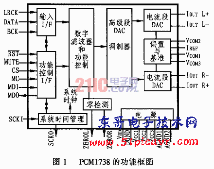
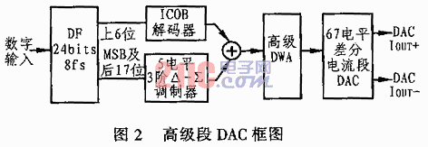
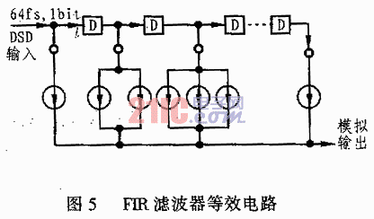
1 Overview This article refers to the address: http:// PCM1718 is another dual-function decoding chip developed by BB Company after the 24-bit/192kHz sinusoidal DAC decoder chip PCM1704 and SACD's DSD decoder chip PCM1700. The chip can decode DVD-Audio's 24-bit/192kHz PCM encoded digital audio signal, and can also decode SACD's 64fs/1bit DSD encoded digital audio with good performance. Therefore, it is an ideal device for developing high-end audio players or performing digital-to-analog conversion. 2 PCM1738 features and performance Figure 1 shows the structural and functional block diagram of the PCM1738. The function description of each pin is listed in Table 1. The main features of the PCM1738 are as follows: â— There is 24 bit resolution on it; â— Take the frequency up to 10 ~ 192kHz; â— With multiple interface formats, 16/20/24bit is the subsequent format, 16/20/24bit I2S, and 24bit is the front-end format. â—The system clock has various options of 128/192/256/384/512/768fs, and the range of fs is 32kHz~192kHz; â— Analog output differential current is ±2.5mA (Iout output); â—Equipped with 8 times oversampling digital filter, you can choose two kinds of ramp-down, fast and slow, and no extra-domain noise rise; â— With digital volume attenuation, soft squelch, zero checkout latch and de-emphasis; â— With DSD mode, and four filter modes to choose from; â— With DF bypass mode, it can isolate the digital filter inside the PCM1738, so that the input signal can be connected with a higher-grade external digital filter; â—Using analog 5V and digital 3.3V power supply; â— Available in a 28-pin SSOP package. Table 1 PCM1738 pin function table Pin number name I/O function 3 PCM1738's advanced segment works The PCM1738's Advance Segment DAC and current segment DAC are a new digital-to-analog conversion method developed by BB for PCM1738. Since the resolution of 24bit is as high as 1/1677216=0.00000006, the accuracy of the components and the circuit structure constrain the final actual accuracy. Under the current state of the art of integrated circuit fabrication, the development of new circuits is a shortcut that can quickly improve the level. The overall principle of the PCM1738 advanced segment DAC is shown in Figure 2. The DAC mode of its advanced stage is mainly composed of an inverting compensated bipolar ICOB decoding part, a 5-level third-order delta-sigma modulation, an advanced segment data weighted average DWA, and 67 level differential current segments. When the digital output data after the format change enters the digital filter, it first transforms into 24bit/8fs data by eight times oversampling, and then splits it into upper and lower segments. The upper segment is the 6-bit data except the highest MSB, and the lower segment is the 18-bit data composed of the MSB and the last 17 bits. In operation, the upper 6 bits are input to the ICOB decoding portion, and the lower 18 bits of data are input to the 5-level third-order delta-sigma modulator. In this way, a coarse waveform of 64 steps can be modulated by the upper 6 bits (m=2 6th power = 64), and the lower 18bit is the residual amount which is not included in the 6 bits in the data. The ICOB (Inverted Complementary Offset Binary) is called Inverted Compensating Offset Binary. It converts 6-bit data without MSB into 64-level data, and then splits it into 63-level working code output suitable for current segment operation. The equivalent circuit of the 5-level third-order delta-sigma modulator is shown in Figure 3. When modulating a signal with a large input amplitude, the movement of each sampling point in the amplitude direction is set at 1 level. Inside. This allows the amplitude to time axis error (caused by the master clock) to be relatively small. The level of the 63-level ICOB digital output and the 5-level third-order delta-sigma modulator output are both 1, and can be directly added to the 67-level ICOB code in the summing circuit, and then Δ- The ∑ modulation signal is transmitted, and finally the digital conversion operation is performed. The digital conversion operation is divided into two steps, namely advanced DWA and current segment DAC. Advanced DWA (Advance Data Weighted Averaging) can be used to generate the most suitable working clock required in the current segment after the digital to analog conversion. To minimize analog error, the PCM1738 combines independent timing control with first-order noise shaping to achieve high-precision, low jitter. The current segment DAC is composed of a balanced differential current portion that is equally weighted by analog and a current switch that controls on/off of the current segment. It is the heart of a DAC that transforms from digital signals to analog signals. Figure 4 is a simplified equivalent circuit of the current segment. It has a total of 75 pairs of differential current sources that can be controlled by input levels and control clocks from 67 levels of advanced DWA to complete the conversion. Since these 75 pairs of current sources have enough margin to handle 67 levels, each current source can operate at its optimum state without mismatch errors in the absence of loud or large amplitudes. In addition to digital-to-analog conversion of DVD-Audio's 24-bit/192kHz PCM encoding, PCM1738 also has the ability to perform digital-to-analog conversion of SACD's DSD direct data stream. The current source structure of Fig. 4 can also be used for digital conversion of a 64fs/1 bit DSD signal. If it is used as an analog FIR filter, the base function is equivalent to the FIR filter shown in Fig. 5. The value of the delay unit D and various current segments is the weight of each section. At this time, each current source operates in a differential manner to obtain a high quality DSD/analog conversion. 4 PCM1738 application circuit Figure 6 shows the application circuit of the PCM1738. The audio data access, working clock, and serial data interface for control have been omitted in the figure, and the actual circuit of the evaluation board of the company is simulated. The analog output of the D/A converter in the PCM1738 is the balanced differential current, which is ±2.5mA at full scale (0dB) and 5mA peak-to-peak. Therefore, a current/voltage (I/V) conversion circuit must be applied during use, and a double-ended/single-ended conversion is required at the same time. When the I0 terminal is at full amplitude, its output Iout is ±2.5mA. The feedback resistors R11, R12, R21, and R22 in the figure are all 620Ω. Thus, the I/V converted voltage V0 will be ±(2.5Rf)mA. . In addition, since the gain of the double-ended/single-ended conversion output with filtering in the latter stage is 1, the actual output voltage becomes the difference between the two input signals. which is: Vout=Vo-(-Vo)=2Vo, This results in an output peak-to-peak value of Vp-p of 2.192 Vrms. The frequency response is determined by the capacitance in parallel with the feedback resistor. The band requirements for the signal should be 100 kHz according to the DVD-Audio and SACD standards. However, it can still be adjusted within a certain range according to needs. The final bandwidth determined by the capacitance resistance value in this circuit is 70 kHz. Aluminum Alloy Die Casting Blank Aluminum Alloy Die Casting Blank,Pressure Die Cast,Die Casting Products Alloy,Molded Precision Die Parts Cast Dongguan Metalwork Technology Co., LTD. , https://www.dgdiecastpro.com

1 RST I reset input
2 ZEROL OL channel 0 logo
3 ZEROR OR channel 0 logo
4 WDCK I WDCK clock input in DFTH mode; grounded in DSD mode
5 DATA IL channel audio data input
6 BCKI I bit clock input in DFTH mode; ground in DSD mode
7 SCKI I is the system clock input in DFTH mode; grounded in DSD mode
8 DGND - Digital Ground
9 VDD - Digital Power Supply (+3.3V)
10 SCKO O system clock output
11 MDO O function control register string data output
12 MDI I function control register serial data input
13 MC I Function Control Register Shift Clock
14 SC I Function Control Register Latch Enable
15 MUTE I is muted in DFTH mode; R channel audio data input in DSD mode
16 IoutR- O Right channel negative current output
17 IoutR+ O Right channel positive current output
18 AGND1 Analog Ground 1
19 VCOM1 - Internal Offset Decoupling
20 VCOM2 - I/V common voltage
21 Iref - Output current reference bias terminal, connect 16kΩ resistor to ground
22 VCOM3 - I/V common voltage
23 Vcc1 - Analog Voltage +5.5V
24 Vcc2 - Analog Voltage +5.5V
25 IoutL+ O left channel positive current output
26 IoutL- O Left channel negative current output
27 AGND2 - Analog Ground 2
28 Vcc3 analog voltage +5.5V 