Overview:
Based on the UCD92xx and UCD7xxx non-isolated digital power supplies, the output voltage often “steps†during the soft start phase, and the waveform is not smooth, especially when the output voltage is set to a low value, such as 1.0V. This "step" phenomenon is related to the design principle of the UCD92xx soft start, but it can be optimized and finally solved by certain measures. This paper optimizes and analyzes the loop and minimum duty cycle width of UCD92xx, and finally achieves the desired effect.
1. Soft start principle and output voltage waveform to be optimized The soft start of the digital power supply UCD92xx is realized by stepping up the reference voltage. The whole process is automatically completed by the software inside the chip. When testing on a board based on UCD9224 and UCD74120, it was found that the output voltage waveform had a significant "step" phenomenon during the soft start phase, and the waveform was not smooth.
1.1 Introduction to the principle of digital power soft start
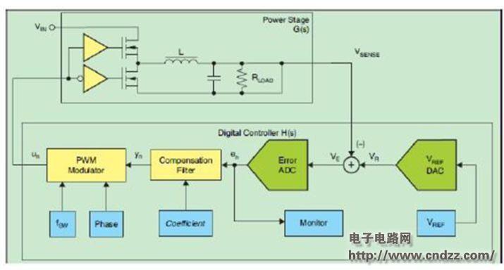
Figure 1 shows the power branch and control branch of the digital power supply UCD92xx. The control branch is mainly integrated inside the UCD92xx chip, including error generation and analog-to-digital conversion, loop compensation, PWM calculation and generation. Among them, the setting of the reference voltage (VREF) voltage is also included in the control branch.
According to the software algorithm, during the soft start phase, VREF is incremented every 100us until the soft start is completed, ie the output voltage reaches the final set value. For example, if the output voltage is set to 1.0V and the soft-start time is set to 4ms, the output voltage is increased by 25mv each time during the soft-start phase until it reaches 1.0V. 
Figure 1: Digital power stage and control level block diagram (please read the PDF for details)
KNLN6-63 Residual Current Circuit Breaker With Over Load Protection
KNLN6-63 TWO FUNCTION : MCB AND RCCB FUNCTIONS
leakage breaker is suitable for the leakage protection of the line of AC 50/60Hz, rated voltage single phase 240V, rated current up to 63A. When there is human electricity shock or if the leakage current of the line exceeds the prescribed value, it will automatically cut off the power within 0.1s to protect human safety and prevent the accident due to the current leakage.
leakage breaker can protect against overload and short-circuit. It can be used to protect the line from being overloaded and short-circuited as wellas infrequent changeover of the line in normal situation. It complies with standard of IEC/EN61009-1 and GB16917.1.
KNLN6-63 Residual Current Circuit Breaker,Residual Current Circuit Breaker with Over Load Protection 1p,Residual Current Circuit Breaker with Over Load Protection 2p
Wenzhou Korlen Electric Appliances Co., Ltd. , https://www.zjmotorstarter.com