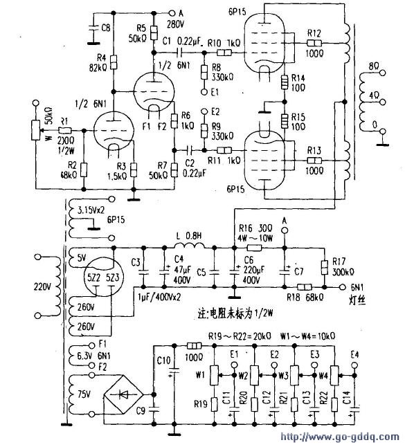
The production steps are as follows: First, according to the basic electrical performance parameters of the tube design, because the anode voltage of 6P15 is 300V to 330V, the current is 30mA, the transconductance is 14.7mAN, and the output power is close to 6P14 and EL84. If the tube is used to make a single end, the output power is small, and it is difficult to push a speaker with two or more frequency divisions, which is obviously not suitable. Therefore, according to the design of the ultra-linear push-pull circuit, 14W output power can be obtained, and the two-way speaker or the three-way speaker of 90DB or more can be promoted to satisfy the listening in the living room or bedroom of about 15 square meters. A simple three-stage amplification is shown in Figure 1. The first stage voltage amplification uses direct coupling to obtain a wider channel frequency, and the second stage is inverted and driven. The 6P14, EL84 and 6P15 are also universally interchanged through some technical measures, and future maintenance and exchange are not restricted by the pipe. Second, the device selects the voltage amplification and inverting part to select the common 6N1, 6N3, 6N4 series double triode (6N1 used). Use 1/2 of the 6N1 double triode for voltage amplification, and another 1/2 for the drive stage to split the phase of the screen, and push the end of the power tube 6P15. The resistance can be as shown in the figure (the 1/2W is not specified), the coupling capacitors C1 and C2 are selected from the oil immersion type of 0.2μF/400V or more, and the metalized paper dielectric capacitor can also be used. Power supply decoupling capacitors use oil-immersed capacitors or metalized paper capacitors to facilitate beautiful sound. Third, push-pull tube gate voltage selection gate negative pressure generally has two ways, one is self-contained gate bias, the second is fixed gate bias. These two methods have their own advantages, the self-biasing bias is almost no adjustment, no need to increase the winding of the transformer, and the grid negative voltage regulating power supply, but the troublesome thing moves to the next step, making the selection or pairing difficulty more difficult. The difference between the fixed gate bias voltage requires that the transformer be wound around a group of 70V ~ 100V windings as a gate negative voltage regulating power supply for the bias voltage of the push-pull tube. Under the same screen voltage, the self-bias voltage is equal to the screen voltage minus the gate voltage, and the fixed bias voltage is a bit like the positive and negative power supply of the OCL circuit, that is, the screen voltage plus the gate negative voltage. Obviously, a fixed bias voltage can increase the supply voltage and increase the output power. When you choose the tube, you don't need to pair it, and you can easily adjust the balance of the two tubes. Especially for amplifiers with low power, in order to increase the output power, it is more reasonable to use fixed gate negative voltage, which is also the reason for selection. Fourth, the power supply requirements and processing power supply seem simple, in fact, it is not a simple link, it will directly affect the performance of the whole machine. According to the sum of the screen current consumption of 4 6P15 tubes, the current of the secondary side high voltage winding of the power supply is determined, and the requirement is greater than 15% to meet the requirements of this circuit. Filament power processing. In order to eliminate the hum, the grounding of the 6P15 filament power supply is grounded. The 6N1 filament power supply is not directly grounded. The method of raising the potential is to connect two resistors through the high voltage power supply and the ground (R17=300kΩ, R18 =68kQ), divide the voltage to obtain a voltage of about 70V, and then connect to the end of F1 of the 6N1 filament to eliminate the hum. Another point that is easily overlooked is that AC-powered filament power lines are prone to magnetic field radiation and produce hum. In this regard, all AC-powered wires must be twisted and routed. The direction of the twisting should be opposite to the winding direction of the transformer. This is an indispensable step to reduce the hum. Five, power transformer and output transformer power transformer power 120W. Output transformer core cross-sectional area 22mmx40mm, primary with φ0.14mm enameled wire wrapped around 900+900+900+900åŒ, secondary with φ0.83mm enameled wire wrapped around 120åŒ (4Ω), 160åŒ (8Ω), silicon steel sheet cross-plug, no Leave an air gap. Sixth, the whole machine debugging should check the correctness of each solder joint before power-on, whether there is a short-circuit in the cross-talk of the connecting line, and the tube is not inserted after the error, and the screen pressure corresponding to each pin is measured. Filament voltage, gate negative voltage, etc., after correct, then adjust the 4 (W1, W2, W3, W4) potentiometers of the gate negative voltage to the middle position, then disconnect the power switch and plug the tube, and the output terminal is connected to the speaker. Avoid burning the output transformer when no load is present. Power on to measure the voltage of each working point, after basically normal, then adjust W1, W2, so that the voltage drop of the resistors R14 and R15 is 025V, the current is 25mA; the right channel adjusts W3 and W4, check every 15 minutes, adjust once, Half an hour later, I listened to a "Folk Song" by Gong Wangyue. The sound is soft and sweet, and every note is very clear and very pleasant. Commutators For The Special Electronic Machines Commutators For The Special Electronic Machines,Motor Armature Commutator,Special Electronic Machines Commutators,Mixer Motor Commutator ZHEJIANG JIAGU ELECTRIC APPLIANCES CO. LTD , https://www.chinajiagu.com