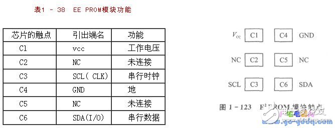
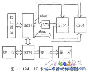
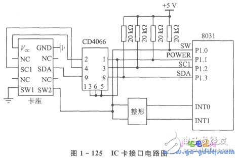
The IC card (Integrated Circuit Card) is an integrated circuit chip embedded in a plastic substrate and packaged in the form of a card. The IC card was first proposed in the early 1970s. It was first created by the French company BULL in 1976 and applied to the financial, transportation, medical, identity card and catering industries. China is committed to the construction of economic information, including the "Golden Bridge", "Golden Card" and "Golden Gate" three gold projects. The "Golden Card" project (electronic money project) is one of the important projects to promote the informationization of China's national economy. It uses magnetic cards or IC cards as the medium, and utilizes the existing network resources of the Ministry of Posts and Telecommunications and the People's Bank of China, and forms an economic information system through the “Golden Bridge†network to serve the banking, business and tourism sectors. Because the IC card is not only waterproof, moisture-proof, anti-magnetic and extremely safe, confidential, anti-counterfeiting, but also has a long service life, it is the first choice for the “Golden Card†project. The IC card chip has the ability to store data for storing data. Depending on the integrated circuit embedded in the card, it can be divided into the following three categories. ◠Memory card: The integrated circuit in the card is E2 PROM; ◠logical encryption card: the integrated circuit in the card has encryption logic and Ez PROM; ◠CPU card: The r integrated circuit in the card includes the central processing unit CPU, E2 PROM, random access memory RAM and solid The on-chip operating system COS (Chip OperaTIng System) in the ROM. The IC card is divided into a contact type IC card and a non-contact type IC card in accordance with the form of external data transmission. Contact type IC cards are widely used at present. Due to the different types of IC cards, there are different read/write modes and hardware requirements. When we developed the IC card reader/writer, we used the AT24COIA memory type IC card produced by American ATMEL. The AT24COIA has a capacity of 1K bits (128&TImes; 8), the number of erasures is 100,000 cycles, and the data storage period is 100 years. The modules used in this IC card comply with the ISO/IEC7816 protocol, and the contact arrangements are shown in Table 1-38 and Figure 1-123. The hardware block diagram of the IC card reader/writer designed in this section is shown in Figure 1-124. The IC card reader/writer circuit is mainly composed of 8031 ​​single-chip microcomputers, supplemented by chips of 2764, 6264, 8279 and so on. The whole circuit is divided into three parts: basic single-chip system, display and keyboard circuit and IC card interface circuit. The basic single-chip system circuit consists of 8031 ​​MCU, 8KROM2764, 8K RAM6264 and 74LS373 for address latching; the display and keyboard circuit consists of 8279 chip, LED display and driver chip. Using 8279 chip can make programming simple and save 8031 ​​hardware resources. The IC card interface circuit consists of a bidirectional analog switch and a pull-up resistor. Because IC cards have their unique electrical characteristics, the hardware circuits must be designed to meet their electrical performance requirements. The hardware circuit designed according to the electrical characteristics of the IC card is shown in Figure 1-125. Since the IC card is a memory chip, if the interface hardware is not properly designed, the IC card life will be shortened, and the IC card will be burned out; and the reasonable design will protect the card, thereby enhancing the read/write reliability of the IC card. And extend the service life. The IC card reader/writer designed in this section takes different measures from various aspects and avoids damage to the card as much as possible. In the process of using the IC card, since the contact type IC card is manually read and unplugged to complete one read/write, the IC card is in an unstable contact state during the plugging and unplugging process. If the interface device of the IC card is charged in this case, it will undoubtedly cause damage to the card. Therefore, during the plugging and unplugging process, the IC card interface device is never allowed to be charged. There is generally one status switch on the card holder of the IC card, and the presence or absence of a card on the card holder can be reflected by the switch signal. Therefore, by judging the switch signal, the presence or absence of the card can be known, thereby controlling the up and down of the lC card interface device. It is judged whether the switch signal can be queried or interrupted. However, the response mode is slow, especially for card pulling. Due to the large randomness of the manual card extraction, if the card is suddenly pulled out during the read/write process, the read/write failure will occur; and because the power of the interface device cannot be removed in time, the lC card is easily damaged. Therefore, the interrupt method is adopted in the design. The switching signals are respectively passed through the AND and NOT gates, and are shaped and added to the two external interrupts INTO and INT1 of the 8031. In this way, as long as the IC card is inserted and removed in an interrupted manner, the IC card can be protected by cutting or turning on the power of the interface device. However, during the plugging and unplugging process, only the power supply is cut off, and the damage to the card cannot be completely avoided. In order to further improve the protection of the card, all the signal lines and power lines that are in direct contact with the card are connected to the IC card through the CD4066 bidirectional analog switch, and the CD4066 is controlled by Pl.1 in Figure 1-125. Turn on, signal and power on and off. In this way, when the card is inserted or removed, the interrupt is responded in time. When there is no card, quickly cut off the signal cable and power cable that are directly connected to the card, and ensure the protection of the card on the hardware. If the IC card and the MCU host share the same set of power supplies, interference will occur between them, especially the host's interference with the IC card. In order to avoid this mutual interference, the dual power supply independent power supply method is adopted in design, that is, the IC card is separately powered by the LM317 high stability power supply, and the host is powered by the 7805. In this way, the two groups of power supplies respectively supply power to the 1C card and the host, which weakens or even eliminates power interference between the IC card and the host, improves the read/write reliability of the IC card, and protects the IC card. UV Screen Protector,UV Curing Machine,UV Curing Screen Protector Shenzhen Jianjiantong Technology Co., Ltd. , https://www.tpuprotector.com

