USB 2.0 Hub
Another version of USB HUB.When comparing 2.0 and 3.0 there are a few major differences. First the transfer rates: USB 2.0 offers transfer rates of 480 Mbps and USB 3.0 offers transfer rates of 4.8 Gbps - that's 10 times faster. Note that the transfer speeds also depend on the device in use in addition to the bus type and USB ports and cables.
USB 2.0 Hub,Macbook Usb Hub,Macbook Pro Hub,Hub for Laptop Pogo Technology International Ltd , https://www.pogomedical.com
Low-voltage differential signaling (LVDS) is ideal for clock distribution and signal transmission from one point to many points. This article describes the method of using LVDS to distribute high-speed signals to multiple destinations.
In a digital system, when each subsystem needs the same reference clock source to work together, clock distribution is very important. For example, the digital signal processing unit (DSP) of a base station must be synchronized by the RF processing unit in most applications. The required local oscillator frequency is generated by a phase-locked loop (PLL) and locked to the clock center frequency by an analog-to-digital converter. At the same time, when the application system contains a radio frequency receiving loop, the clock (including the signal part) must reduce the level radiation in the transmission process as much as possible, and use a lower level to avoid interference.
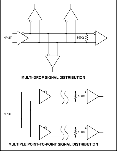
When transmitting high-speed signals to different destinations, a variety of strategies can be used; there are two extreme forms in these schemes: one, use one source / driver to drive all target ends (called multi-node transmission); two, each The target uses an independent source / driver (called multiple point-to-point transmission). Figure 1 shows the difference between transmission schemes using two different technologies. In the multi-node transmission mode, a driver with sufficient driving capacity is required to drive all loads and transmission media (cables, connectors, backplanes, etc.). The differential bus is usually terminated at the last receiver according to the characteristic impedance. Efforts must be made to make the branches on the bus as short as possible to avoid affecting signal integrity. With the increasing wiring density of circuit boards, it is difficult to control the branch length in some cases. 
Figure 1. Multi-node signal transmission allows communication between a single transmitter and multiple receivers, and the multi-point point-to-point transmission method does not require adjustment of the branch circuit, eliminating the potential interference problem of the branch circuit.
Correspondingly, the multiplex point-to-point transmission method uses multiple drivers. It is only necessary to specify the point-to-point operation mode, and each driver only communicates with a single receiver. Using this design architecture can avoid signal integrity issues and ensure that the impedance of the transmission medium is as consistent as possible.
The MAX9150, a low-jitter 10-port LVDS adapter that will be described below, can be used for multipoint point-to-point signal transmission.
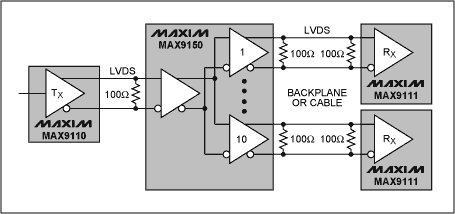
The MAX9150 LVDS adapter MAX9150 is suitable for high-speed data or clock transmission applications that require stringent power consumption, board space, and noise. The IC in Figure 2 can receive 1 LVDS signal and drive it to 10 LVDS outputs. 
Figure 2. The MAX9150 LVDS adapter can drive the received input signal to 10 outputs. The MAX9110 converts the CMOS signal at its input to a differential signal. The MAX9111 converts the respective LVDS differential signal to a CMOS level signal.
The input of the MAX9150 can accept differential signals with a minimum amplitude of 100mV and a maximum of 1V. The input signal level is required to be in the range of 0 to 2.4V. Current output is used to generate 5 to 9mA current output. Because the MAX9150 outputs a current signal, the differential level range of the output signal is determined by the resistance of the external termination resistor. Each differential output is designed to drive a 50Ω load, allowing point-to-point transmission of signals on 100Ω matched transmission lines at both ends. . The device has 120ps jitter (randomness and determinism), which is applied to high-speed interconnection systems sensitive to timing errors to ensure the reliability of communication, especially the clock information embedded in the encoded signal. The high-speed switch ensures a data transmission rate of 400Mbps and a channel-to-channel deviation of less than 100ps. The working power of MAX9150 is 3.3V, and the maximum current consumption is 160mA when the transmission signal is 400Mbps. The low-power shutdown mode can reduce the supply current to 60µA. When there is no input drive or an open circuit occurs, the termination resistance fails or shorts, the failure protection circuit in the device can set the output terminal to a high level.
Table 1 highlights the key parameters of the MAX9150.
Table 1. MAX9150 jitter specifications DifferenTIal PropagaTIon Delay Total Peak-to-Peak Jitter DifferenTIal Output-to-Output Skew (same device) Rise / Fall Time Maximum Input Frequency
Maxim's other LVDS devices Table 2 lists some of Maxim's LVDS devices. These devices can be used with the MAX9150 or can be used alone. Figure 2 shows an example of two devices used with the MAX9150. In this application, the MAX9110 converts the CMOS level into an LVDS signal and provides it to the MAX9150. At the end of the transmission line, the MAX9111 receiver in a SOT23 package converts the LVDS signal back to the CMOS level.
Table 2. Maxim provides a large number of LVDS ICs, including receivers, drivers, adapters, crossbar switches, bus serializers, etc. MAX9111 / 3 Single / Dual LVDS Line Receivers with Ultra-Low Pulse Skew in SOT23 MAX9110 / 2 Single / Dual LVDS Line Drivers with Ultra-Low Pulse Skew in SOT23 MAX9150 Low-Jitter, 10-Port LVDS Repeater MAX9115 Single LVDS Line Receiver in SC70 MAX9121 / 2 Quad LVDS Receivers with Flow-Through Pinout and Integrated Termination MAX9124 Quad LVDS Line Driver MAX9125 / 6 Quad LVDS Line Receivers with Integrated Termination MAX9152 800Mbps LVDS / LVPECL to LVDS Crosspoint Switch MAX9205 / 7 Bus LVDS Serializers
Conclusion When the signal transmission rate reaches tens to hundreds of MHz, LVDS devices are usually a better choice than TTL signal transmission. The differential characteristics fundamentally enhance the ability to resist common mode interference and reduce noise. Compared with other transmission methods (such as ECL, CML, etc.), low power consumption is also a feature of this transmission method. Of course, the overall power consumption of the circuit usually depends on the termination technology selected. Integrated circuits based on LVDS technology are suitable for many applications, including clock distribution and serial data signal transmission up to 400MHz. The above-mentioned Maxim's LVDS device only generates very low phase jitter and a small amount of power consumption when transmitting these signals, and has extremely low interference. Two signal transmission methods are shown here: multi-node transmission and multi-point transmission. Each transmission method has its own advantages and disadvantages.
The MAX9150 chip forms the core of a high-speed data or clock distribution system, and other LVDS devices (such as single / multiple drivers, etc.) are used to complete specific functions of the circuit. Maxim also provides LVDS crossbar switches, bus serializers, etc.

High-speed signal transmission through low-voltage differential signaling (LVDS)
Abstract: The Low Voltage Differential Signaling (LVDS) defined by the ANSI EIA / TIA-644 standard is ideal for signal distribution including clock distribution, point-to-point, and multipoint. This article describes how to use LVDS to distribute high-speed communication signals to multiple destinations.
Parameter
Value
2.2ns
20ps
40ps
220ps
400Mbps minimum
Part
Description