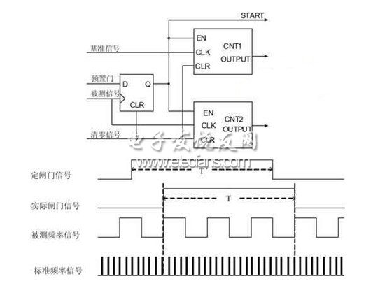
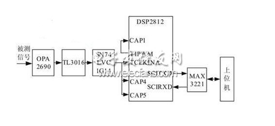
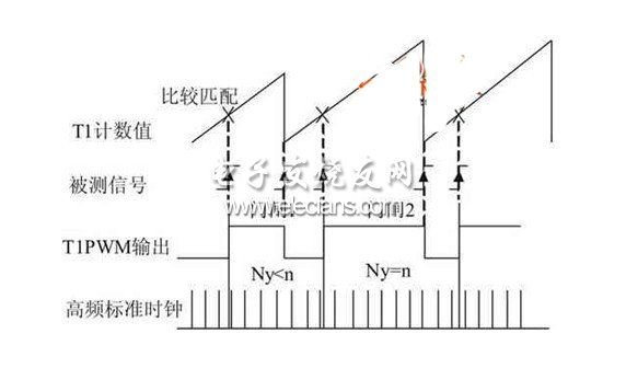
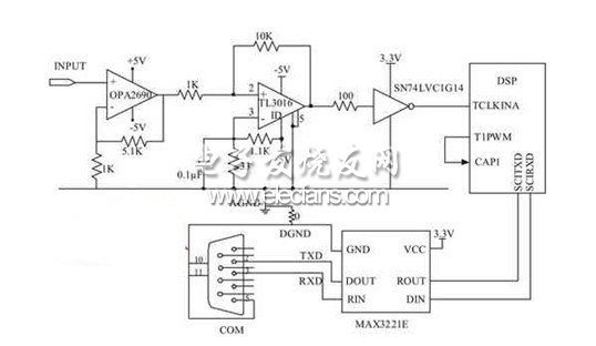
With the rapid development of microelectronics and computer technology, various electronic measuring instruments have undergone tremendous changes in terms of principle, function, precision and automation level. Especially after the birth of DSP technology, electronic measuring technology has entered a new A new era. In recent years, DSP has gradually become the basic device of various electronic devices, and has gradually become the sunrise industry with the most development potential in the 21st century, and is even hailed as the revolutionary standard bearer of the digital age of information. In electronic measurement technology, frequency is one of the most basic parameters, and it has a very close relationship with many electrical and non-electrical measurements. For example, many sensors convert some non-electricity into frequency for measurement, so the measurement of frequency is more important. A digital frequency meter is an instrument that uses a digital display to indicate the frequency of a signal under test. The measured signal can be a sine wave, a square wave, or other periodically varying signal. Digital frequency meters are widely used in high-speed integrated circuits and large-scale integrated circuits, making the instrument smaller, consume less power, and have higher accuracy and reliability. The traditional frequency meter has a large measurement error and a narrow range, so it is gradually replaced by a new digital frequency meter. DSP-based equal-precision frequency meters will be widely used due to their advantages of accurate measurement, high precision, convenience, and low price. The simple digital frequency meter we designed achieves equal-precision frequency measurement over a wide range without any gated device control. The maximum relative error of the measured square wave in the range of 0.5Hz~10MHz is less than 2e-6. The maximum relative error of the measured sine wave is less than 3.5e-5; the result is displayed on the computer through RS232 communication, and the data can be conveniently monitored. Design General introduction The traditional equal-precision frequency measurement method uses a gated device to generate a gate signal, thereby realizing the synchronization of the actual gate signal with the signal to be measured, and eliminating the error of one pulse generated by counting the signal to be measured. The schematic diagram is shown in FIG. Figure 1 Traditional equal precision measurement principle The gate time counted by the hardware control, when the preset signal (ie, the fixed gate signal) is high, the reference signal counter CNT1 and the signal counter CNT2 to be tested are not activated, but wait for the rising edge of the signal to be measured. At the same time, the counting starts at the same time; when the preset signals are low, the two counters are not immediately turned off, and also wait until the rising edge of the measured signal comes and then closes; thus, the actual gate time is the integer of the measured signal period. Double, thus achieving synchronization of the gate with the signal under test. However, the actual gate time is not fixed and is related to the frequency of the signal being measured. In addition, whether using a counter or a single-chip microcomputer, it is always inseparable from the gate device when achieving equal accuracy measurement. This design is based on DSP's rich software resources. After judgment and processing, it has completed the measurement of the accuracy of the measured signal frequency. The circuit is simplified without the need for any gated devices on the hardware. The system block diagram is shown in Figure 2. The signal processing part uses the TMS320F2812 DSP chip as the core of control and measurement; the signal conditioning part mainly completes the amplification, shaping and limiting of the signal; the standard frequency signal is generated by the 30MHz active crystal oscillator as high The frequency standard fills the pulse; the SCI module of the DSP communicates with the host computer, and the result is displayed on the host computer. Figure 2 system block diagram Frequency/Period Measurement In the measurement of the frequency and period of the signal under test, the equal-precision measurement is based on the transition of the output level of the T1PWM pin when the DSP compares the match as the opening and closing of the gate signal, since the comparison match occurs at the measured The rising edge of the signal, thus achieving the synchronization of the gate time with the signal under test. The schematic is shown in Figure 3. Figure 3 Principle of this precision frequency measurement The general-purpose timer T1 clock input selects the external timer clock. Here, the conditioned signal is used as the clock input of the timer T1. The timer T2 clock input selects the internal CPU clock to generate the high-frequency standard fill pulse. When the compare timer event occurs on the F2812 on-chip EVA general-purpose timer T1, the comparison output pin T1CMP output signal will automatically change the level state to generate a PWM wave. The capture unit CAP1 is set to capture on the rising edge. The rising edge of the PWM wave of the T1PWM output is captured by CAP1. The count value of the timer T2 is read at this time. Similarly, the count value of the timer T2 is read again in the next comparison match. By subtracting the T2CNT values ​​twice, the number of standard fill pulses in the gate time can be obtained, and then the frequency of the signal to be measured is obtained. The transition of the T1PWM pin output level based on the DSP comparison match is used as the opening and closing of the gate signal. Since the comparison match occurs on the rising edge of the signal under test, the gate gate time is synchronized with the measured signal. The rising edges of the PWM waves generated by the two adjacent comparisons are respectively used as the on and off signals of the gate signal, wherein the number of signals to be measured is an integer and is arbitrarily set by ourselves. The timer T2 clock input selects the internal CPU clock to generate a standard fill pulse. Set the capture unit CAP1 to capture on the rising edge. When it captures the rising edge, it reads the value in the stack CAPFIFO. After the next capture, it reads the value in the stack and calculates the number of standard fill pulses Ny to ensure Ny. If the number is not less than a certain value, the gate time can be guaranteed to be greater than a certain value. Suppose now that the total number of high-frequency fill pulses in a gate time is not less than n. When Ny>n, the timing period of the timer T1 is increased, that is, the value of the timer T1 period register TIPR is increased. There is a formula T1PR+1=n/Ny, since n/Ny is not necessarily an integer, false a The basic principle of period measurement and frequency measurement is exactly the same. The signal frequency is measured. According to the common T=1/f, the period of the signal to be measured can be obtained. The start and stop time of the error analysis timer T1 is triggered by the rising edge of the signal. There is no error in the counting of the measured signal in one measurement time; during this time, the number of counts of the standard frequency pulse is Ny, the maximum difference A pulse, so the theoretical error is: |d|≤1/Ny Obviously, the measurement accuracy is only related to Ny, as long as the Ny value is large enough to ensure accuracy. hardware design As shown in Figure 4, the signal to be measured is amplified by the high-speed op amp OPA2690, and is shaped by the high-speed comparator TL3016 [3]. Since the comparator shapes the low-frequency sine wave signal, the edge of the output waveform is more serious. Jitter, affecting the measurement. The solution is to add positive feedback to the comparator, accelerate the edge of the signal, and form a hysteresis, which can effectively eliminate jitter. The shaped signal is clipped and further shaped by the high speed Schmitt trigger SN74LVC1G14. The measurement part mainly uses the clock input pin TCLKINA of the timer T1 on the DSP2812 chip, the comparison output pin T1PWM of the timer T1, and the input pin CAP1 of the capture unit CAP1 to complete the frequency measurement. The communication part selects the MAX3221 as an RS-232 level conversion device, and serially communicates with the host computer through a 9-pin standard RS-232 port. The serial communication transmission pin SCIRXD and the serial communication reception pin SCITXD of the DSP are mainly used. Ningbo Autrends International Trade Co.,Ltd. , https://www.mosvape.com


Figure 4 hardware circuit connection diagram