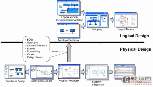
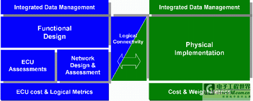
Design and implementation architecture of distributed automotive electrical / electronic systems In the past ten years, the electrical and electronic systems of automobiles have become very complicated. Today, automotive electronics / electrical system development engineers widely use model-based functional design and simulation to meet this complexity challenge. Emerging standards (such as AUTOSAR) define standardized interfaces with low-level software, and most importantly, it also introduces a new level of abstraction for functional implementation engineers. This improves the reusability of software components, but unfortunately there is little guidance on how to convert the results of model-based functional design into a reliable and efficient system implementation in a highly distributed environment. In addition, there are very few articles on the physical side of the design process. This article outlines a recommended system-level design methodology, including architecture design, network and task scheduling across multiple ECUs, harness design, and specification generation. Why do you need AUTOSAR? Even in the same company, "architectural design" has different meanings to different people, depending on which angle they stand on. The physical architecture deals with the physical aspects of the system, such as wiring and connectors, and the logical architecture defines the structure and distribution of intangible systems, such as software and communication protocols. At present, the language for designing physical architecture and logical architecture is independent, which leads to the meaning of the same word can be completely different, the design team and the process are also independent, which also leads to a very complex design process (as shown in Figure 1). Figure 1: Physical and logical design flow. This complexity leads to sub-optimal design results. The correct function of the entire system is so difficult to implement that there is little time to find an alternative method, which can lead to more robust, more scalable and more Cost effective solution. In order to achieve such a solution, designers need new methods that can closely link the physical and logical design processes and still allow different design teams to do their work. The emerging AUTOSAR standard provides a technically and economically feasible option for system-level automotive electronics / electrical design methodology, although it is primarily aimed at the software level, that is, the design of logic systems. However, the extensive and extensive AUTOSAR metamodel and its rich interface definitions allow system-level electronic / electrical architects to express his design ideas in a standard format. From an economic point of view, the AUTOSAR standard opens a huge, unified market, which makes it possible to create suitable design tools. This paper describes a system-level design method composed of point tools based on AUTOSAR. This leads to the use of standards in all meaningful places throughout the entire process, but it is not limited to standards or requires users to adopt these standards. Working principle of AUTOSAR The AUTOSAR standard was initiated by automotive manufacturers, suppliers, and tool suppliers, and aims to standardize the open software architecture of automotive electronic control units (ECUs). The AUTOSAR standard specifies a layered software architecture that clearly defines the interface between application software components (SWC), user-visible automotive functions, and the implementation of infrastructure components. It has strict regulations on infrastructure components to allow components developed by different vendors to work together. User-visible automotive functions are implemented through interconnected application software components. SWC is the smallest unit that can be mapped to the ECU. In order to make SWC independent of specific hardware, the concept of virtual function bus (VFB) is defined. Here, SWC uses VFB to communicate with their environment. This concept supports SWC's repositioning to different ECUs, thereby enhancing the reusability of application software. An AUTOSAR system is basically defined by the following three XML files: SWC description, ECU resource description, and system configuration description. These documents describe all aspects of a logical architecture: SWC, functional network, topology, and function to ECU mapping. Although the syntax and semantics of these files are defined by the AUTOSAR standard, their creation methodology is left to the tool supplier. User case analysis The following two representative user cases can give you a deeper understanding of the complexity of the overall physical and logical design tasks. In the design flow shown in Figure 2, you can see how the logical design process drives the physical design process. The first step in this design process is the definition and implementation of automotive logic functions. Most OEMs break down a car's electrical system into about 100-200 functions. Users create unit-level SWCs that can express various automotive functions, or call such SWCs from model design tools like Matlab / Simulink. Because the specification and development of SWC are highly dispersed in time and place, and many SWCs enter the design process from many different sources, a consistency check should be conducted to find errors as early as possible. Even if there is only an interface description, it is already possible to perform a static check of the interface consistency between internal components. At this point in the design flow, it is important to add end-to-end timing requirements to support advanced analysis tools that require timing information in subsequent flows. Figure 2: User case 1-logical design drives physical design. At the same time, a potential topology can be created, which can outline the logical topology of the distributed automotive network and describe the connections between sensors, actuators and ECUs. Usually, a car project starts with the reuse of the original design and then modify it. When reusing existing ECUs, very detailed ECU information can come from an enterprise database, or a new ECU needs to be defined, and its technical characteristics change during a specific period in the development process. In the above two cases, functional information and topology information can be provided to the physical design process. The functional level of the physical design process also requires data on the ECU (as used by the bus system). The current physical design requires a subsystem design step. At this step, before the physical components are mapped to the packaging space (slot) on the car, subsystems such as ECUs and fuse boxes require further detailed design. In addition to this, the power / ground concept can also be developed at this step. The corresponding step in the logical architecture design is the SWC mapping to the ECU. This also determines the communication scheme between SWCs, that is, whether multiple SWCs communicate through a bus system or an internal ECU. The choice of communication method has a direct impact on the physical design, which also increases the complexity of the entire design process. For example, it depends on whether wires, conventional wires, twisted pairs or twisted pairs are required. The packaging step is followed by physical system integration. Here, the CAD system information is used to add additional physical information, such as the required online connectors and routing channels. This in turn has an impact on the logical level of the design and again increases the complexity of the entire design process. Too small a routing channel may make it impossible to use twisted pair, or too long wire length may make repositioning a SWC to another ECU a more cost-effective alternative. When both physical and logical processes can provide results, their various data can be used to evaluate and optimize the automotive architecture. However, due to the complexity of the process, it is difficult to find more than one working architecture. As a result, logical and physical designers can only try to optimize the parts of their design that they are responsible for. Figure 3: User Case 2-Physical design drives logical design Figure 3 shows the design flow of the physical design driving the logical design. The logical topology is a derivative of the physical topology. Unlike the previous added information, unnecessary information here needs to be filtered. For example, when the physical design of a cigar lighter is required, this function does not require a SWC description, so this information is not required in the logical domain. These two examples only reflect a small part of today's design process challenges and illustrate the complexity of the entire process. Integration of physical and logical design processes One option to improve this inherently complex design process (multiple design teams working simultaneously on the same overall design) is the close connection between two different design processes. Throughout the design process, data needs to be kept in sync, but at the same time, engineers are too hindered by this synchronization. In the current workflow, all people share the same data objects, and they must be checked before using them. An alternative workflow is to use two independent databases for two different design processes ( (See Figure 4), but found a way to keep the data synchronized without a lot of human workload. This requires such a design process, most of the design is actually automatically generated, rather than manually generated. Changes in the database during synchronization will automatically result in a "synthetic" operation, thereby completely avoiding the task of repeating previous efforts. Figure 4: Parallel processing physical and logical design An example is the generation of network configuration. When the signal that needs to be transmitted through the network changes, the designer can manually enter these changes and manually run all the necessary verification tests, which can lead to a lengthy design process time of several months. In sharp contrast to this, various communication data can be automatically generated based on communication requirements and mathematical algorithms, which can greatly reduce the time required to complete the design process to the second level. A similar physical design example is system integration. When the system changes (such as different routing channels), the manual process takes too much time and is prone to errors. By using an automatically generated process, system changes can be processed more or less immediately through the process. For example, the installation position of the connector changes and the wire length can be automatically generated. Here, the engineer's know-how is used to define rules rather than applying them.
The automobile cable is a kind of connecting wire inside the automobile, which is mainly used for current transmission of batteries, instruments, lamps, etc. Due to the particularity of the automobile industry, the manufacturing process of automobile cables is also more special than other ordinary wires. In most cases, it is required that the car cable will be cold and high temperature resistant.
Automobiles Wire,Automobile Insulated Wire,Pvc Insulated Automobile Wire,Automotive Copper Wire Ruitian Cable CO.,LTD. , https://www.rtlinecable.com
