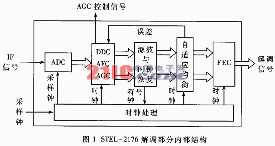
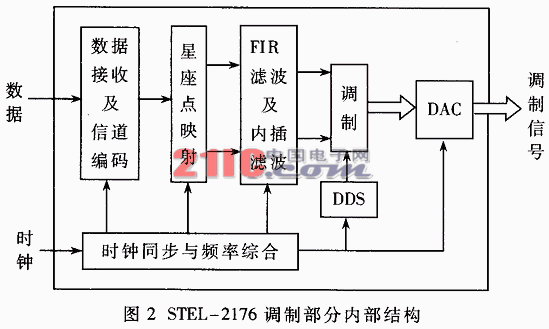
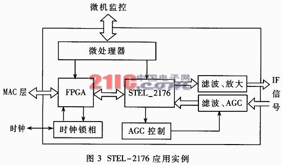
Keywords: broadband wireless access, all digital modulation and demodulation, asymmetric transmission 1 asymmetric transmission Point-to-multipoint base station/user station mode is commonly used in broadband wireless access systems. In most cases, the amount of downlink data from the base station to the subscriber station is much larger than the amount of uplink data from the subscriber station to the base station. If the uplink and downlink occupy the same resources, it is bound to be wasted. In the TDMA/FDD mode, a feasible transmission mode is: the uplink data adopts the burst data packet mode, and the modulation mode with relatively low modulation efficiency (such as QPSK) is adopted; the downlink data adopts the broadcast mode, and the modulation efficiency is relatively high. Modulation method (such as 16QAM). The advantage of the asymmetric transmission is that, on the one hand, the bandwidth can be dynamically allocated according to the actual needs of the user to improve the spectrum utilization efficiency; on the other hand, the number of bits per symbol transmission of the uplink signal is reduced, thereby reducing the base station burst solution. The difficulty of tuning the algorithm. A modem for a subscriber station that satisfies the above requirements must have the capability of demodulating a wideband continuous signal with high modulation efficiency (such as 16QAM) while modulating a broadband burst signal with relatively low modulation efficiency (such as QPSK). . Developing the STEL-2176 is a good choice. The STEL-2176 is an all-digital modem that is compatible with IEEE802.14, MCNS and DAVIC standards. The demodulation part can directly input the intermediate frequency analog signal up to 50MHz, the signal bandwidth can reach 8MHz, and the continuous signal of 16/64/256 QAM can be demodulated; the modulation part can output continuous/burst signals of 5MHz~65MHz, and the modulation mode can be BPSK/QPSK/16QAM with a maximum speed of 40Mbps (16QAM). 3 STEL-2176 internal structure 3.1 Demodulation section Figure 1 shows the internal structure of the STEL-2176 demodulation section, mainly by ADC (analog-to-digital conversion) module, DDC (digital down conversion) / AFC (automatic frequency control) / AGC (automatic gain control) module, filtering and clock recovery module , adaptive equalization, FEC (forward error correction coding) module and clock module. ·ADC module The analog-to-digital conversion module receives an intermediate frequency analog signal with a center frequency of up to 50 MHz input to the STEL-2176, and obtains a sub-IF digital signal with a center frequency of 6 MHz to 7 MHz after band-pass sampling. ·DDC/AFC/AGC module The AFC coarsely estimates the signal carrier, and then the carrier error signal fed back by the back-end adaptive equalizer fine-tunes the carrier local oscillator frequency to obtain the relevant carrier. The DDC receives the 6MHz~7MHz sub-IF digital signal, and demodulates the I and Q baseband signals through the relevant carrier. At the same time, the AGC control signal is output to control the signal strength of the off-chip intermediate frequency and radio frequency analog signals. ·Filtering and clock recovery module The I and Q baseband signals are cancelled by the SRRC (root mean square raised cosine) filter with alpha=0.12~0.20, and the symbol rate is recovered from the signal, and the error is less than 100PPM. ·Adaptive equalization In addition to eliminating various interferences of the channel (multipath effect, amplitude modulation interference, frequency modulation interference, phase noise, etc.), adaptive equalization also feeds back the carrier error signal to fine tune the phase difference and small frequency difference of the carrier. ·FEC module The forward error correction coding module receives the demodulated I and Q signals, performs constellation point mapping, recovers data, and then demodulates the frame structure corresponding to the modulation end, and sequentially performs deinterleaving, channel decoding (RS code), and descrambling. The original signal is output in serial or parallel mode, and the signal of the MPEG-2 structure can be output. The clock module generates various clock signals required for the demodulation portion from the sampling clock and the recovered symbol clock. 3.2 Modulation section Figure 2 shows the internal structure of the STEL-2176 modulation part, which is mainly composed of data receiving and channel coding module, constellation point mapping module, FIR filter and interpolation filter, modulation module, DAC (digital-to-analog conversion) module, clock module, etc. . ·Data receiving and channel coding module The serial input raw data is received for channel coding (RS code), including interleaving and scrambling, which are optional. ·Constellation point mapping module The serial bit stream is mapped to the constellation point of the specified constellation, and is outputted by I and Q. ·FIR filter and interpolation filter The I and Q signals are filtered by a shaping filter (32-stage FIR filter) and output to an interpolation filter. The interpolation filter greatly increases the sampling frequency of the signal to meet the requirements of more than 2 times the carrier signal, matching the rate required for quadrature modulation. ·Modulation module The modulation module is a quadrature modulator composed of a DDS (Direct Digital Synthesizer) and a multiplier. The I and Q signals are respectively multiplied by the SIN and COS carrier signals generated by the DDS, and are combined and output. ·Digital to analog conversion module Finally, the digital signal is converted into an intermediate frequency analog modulated signal output. The signal at this time has an image signal relative to the main clock frequency, that is, the output analog signal requires off-chip filtering. ·Clock module The clock module synchronizes with the external clock and produces the various clock signals required for the modulation portion. 3.3 Monitoring section The status information is transmitted by receiving an external configuration command serially or in parallel through the monitoring module of STEL_2176. Monitoring of STEL_2176 is achieved by accessing its internal registers. 4 STEL-2176 technical features The STEL-2176 utilizes all-digital modulation and demodulation technology to provide advantages in system stability, reliability, and flexibility in transmission rate, carrier rate, and modulation mode compared to conventional modems. 4.1 Highly integrated, low power chip technology STEL-2176 uses 0.35μm linewidth CMOS chip technology, high integration, improve system stability and reliability; operating voltage is lower +3.3V, greatly reducing chip power consumption, and flexible at the interface An optional I/O voltage (+5V/+3.3V) is available. 4.2 Wideband ADC/DAC This is the iconic technology of all-digital modulation and demodulation technology. Whenever possible, the analog signal is converted into a digital signal at the front end of the signal channel to fully utilize the role of digital signal processing technology. The STEL-2176 features a 10-bit ADC and DAC that can handle analog signals in the near 10 MHz bandwidth. Because of the bandpass sampling technique, the analog signal center frequency can reach tens of megahertz. 4.3 Using DDS technology and multi-rate signal processing algorithms All-digital modems typically use DDS technology and multi-rate signal processing algorithms to provide a nearly continuous clock signal of various frequencies at a single reference clock. Because the reference sources are the same, these clocks are frequency dependent. With these clock signals, different carrier frequencies, bit rates, and control signals can be obtained. In addition, when the transmission signal is processed in the digital baseband, the multi-rate signal processing algorithm such as decimation and interpolation is used to achieve the matching of the signal rate between different digital processors. This enables multiple modes of the transmitted signal and multiple modes of the modulated signal. 4.4 Digital Demodulation Algorithm For the receiving part of a communication system, the most important thing is synchronization, so recovery of carrier and timing is necessary. The core of digital demodulation algorithms is carrier and timing recovery, which is a key issue in the design of all-digital modems. STEL-2176 first restores the timing, and uses the complete feedback structure for carrier recovery on the basis of timing: firstly use the NDA (non-data assisted) algorithm to make a rough estimate of the large frequency difference, and the estimated error is fed into the AFC (automatic frequency). Control) Make the local oscillator track a large frequency difference, then use the DD (data-oriented) algorithm to estimate the phase difference and small frequency difference, feed the PLL (phase-locked loop) to control the local oscillator, and track the residual phase difference of the modulated signal carrier. The STEL-2176 digital demodulation algorithm is characterized by the fact that a known information symbol, the preamble, is not needed, but the amount of computation is large, and the time for restoring synchronization is long, and it can only be used for a continuous demodulator. 5 STEL-2176 application examples in broadband wireless access systems Figure 3 shows a block diagram of a subscriber station modem in a point-to-multipoint broadband wireless access system. The microprocessor AT89C51 completes the monitoring and configuration of the system, including the configuration of the operating parameters of the STEL-2176 and the loading of the initial parameters of the FPGA. The FPGA completes the interaction with the MAC layer. The receiving end STEL-2176 is set to input an intermediate frequency analog signal of 44 MHz, the information rate is 9.92 MHz, and the demodulation mode is 16QAM. The IF signal is input to the STEL-2176 after passing through the bandpass filter and AGC. The data output from the STEL-2176 and the demodulation clock are input to the FPGA for baseband processing. The transmitting end STEL-2176 is set to output an intermediate frequency analog signal of 44 MHz, the information rate is 5.12 MHz, and the modulation mode is burst QPSK. The FPGA performs baseband processing, generates burst data packets, outputs to STEL-2176, and controls the STEL-2176 output signal. The intermediate frequency analog signal is filtered and amplified and output to the ODU (outdoor unit) device. The system additionally adopts STEL-1109 as the base station downlink modulator to complete the continuous modulation of 16QAM. STEL-9257 is used as the base station uplink demodulator to complete the QPSK burst demodulation to form a complete point-to-multipoint transmission of asymmetric transmission. Broadband wireless access systems have proven that system solutions are feasible. The system uses a series of devices such as STEL-2176 and FPGA, which greatly simplifies the system hardware and improves the reliability and stability of the system. In addition, because the STEL-2176 has high spectrum utilization efficiency and flexible configuration, it is very convenient and effective to use STEL-2176 as a modem for the subscriber station in a point-to-multipoint broadband wireless access system. 
2 Introduction to STEL-2176 
·Clock module 
The advantages of this flexibility are fully demonstrated in the application of STEL-2176.
Application of all-digital modem STEL-2176 in asymmetric transmission system
Abstract: This paper introduces the structure, function and technical characteristics of the all-digital modem STEL-2176, and gives an application example of it in the point-to-multipoint broadband wireless access system. In this system, STEL-2176 is used as the modem of the subscriber station, and the digital transmission of the 16QAM signal and the digital modulation of the QPSK signal are realized by the asymmetric transmission mode.